
System Design
This section describes the system configuration with this product and peripheral equipment.
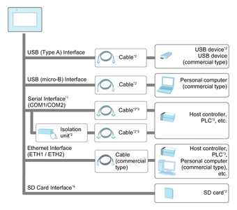
*1 In order to use this as an isolation port, Isolation Unit is required. To use RS-232C isolation unit, set the #9 pin of the COM port to VCC.
*2 Refer to Accessories.
*3 For information on how to connect controllers and other types of equipment, refer to the corresponding device driver manual of your screen editing software.
*4 ST-6500TA only
To
use this product, transferring project data from the screen editing
software is required. For details about transfer, refer to the software
manual.
When transferring using the USB (micro-B) interface, connect cables in the
following order:
-
Attach the transfer cable to the USB (micro-B) interface of this product.
-
Attach the power cable to this product, then connect the power cable to an external power source.
-
Connect the transfer cable to the computer.
 WARNING WARNING |
|---|
|
UNINTENDED EQUIPMENT OPERATION
Failure to follow these instructions can result in death, serious injury, or equipment
damage.
|