
Connecting the DC Power Cord
 DANGER DANGER
|
|---|
|
HAZARD OF ELECTRIC SHOCK, EXPLOSION, OR ARC FLASH
Failure to follow these instructions will result in death or serious injury.
|
-
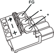
The SG (signal ground) and FG (functional ground) terminals are connected internally in this product.
-
When the FG terminal is connected, be sure the wire is grounded. Not grounding this product can result in excessive electromagentic interference (EMI).
DC Power Cord Preparation
-
Make sure the ground wire is either the same or heavier gauge than the power wires.
-
Do not use aluminum wires in the power supply's power cord.
-
To prevent the possibility of a terminal short, use a pin terminal that has an insulating sleeve.
-
If the ends of the individual wires are not twisted correctly, the wires may create a short circuit.
-
The conductor type is solid or stranded wire.
-
Use copper wire rated for 75 °C (167 °F) or higher.
|
Power Cord Diameter |
0.75...2.5 mm2 (18...13 AWG)*1 |
|
Conductor type |
Solid or stranded wire |
|
Conductor length |
|
|
Recommended Driver*2 |
SZS 0.6x3.5 (1205053) |
|
Recommended Pin Terminals*2 |
3201288 AI 0,75-10 GY 3200182 AI 1 -10 RD 3200195 AI 1,5 -10 BK 3202533 AI 2,5 -10 BU |
|
Recommended Pin Terminal Crimp Tool*2 |
CRIMPFOX 6 |

*1 For UL compatibility, use AWG 14 or AWG 13.
*2 Items are manufactured by Phoenix Contact.
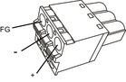
DC Power Supply Connector Specifications: Spring Clamp Terminal Blocks
Models except for SP-5400WA come with the right-angle-type power connector, and the SP-5400WA comes with the straight-type power connector.
|
Connection |
Wire |
|---|---|
|
+ |
12...24 Vdc |
|
- |
0 Vdc |
|
FG |
Grounded terminal connected to the panel chassis. |
-
You cannot connect the right-angle type to the SP-5400WA.
-
Right-angle type: PFXZCBCNDC2 by Pro-face.
Straight type: PFXZCBCNDC1 by Pro-face.
How to connect the DC Power Cord
|
Step |
Action |
|---|---|
|
1 |
Confirm the power cord is not connected to the power supply. |
|
2 |
Check the rated voltage and remove the “DC24V” sticker on the DC power supply connector. |
|
3 |
Connect each wire from the power cable to a pin terminal. |
|
4 |
Push the Opening button with a small and flat screwdriver to open the desired pin hole. |
|
5 |
Insert each power cord wire into its corresponding hole. Release the Opening button to clamp the wire in place. When using stranded wire, do not short with neighboring wires. |
|
6 |
After inserting all three power cord wires, insert the DC power supply connector into the power connector on this product. NOTE: When using the DC power connector
with screws by Pro-face (model number CA7-ACCNL-01 or PFXZCHCNDC3),
use a slot-head screwdriver to affix the screws on both sides of the
connector. The necessary torque is 0.5 N•m (4.4 lb-in).
|
-
Do not solder the wire directly to the power crimp pin.
-
If the wire is not inserted into the FG terminal properly, touch may not respond normally.