
Serial Interface (RS-232C and RS-422/RS-485) for COM1/COM2
Introduction
You can switch the communication method between RS-232C and RS-422/RS-485 via the software.
The serial interface is not isolated. The SG (signal ground) and FG (functional ground) terminals are connected inside this product. When the serial interface connector is D-Sub, connect the FG wire to the shell.
 DANGER DANGER
|
|---|
|
ELECTRIC SHOCK AND FIRE
When using the SG terminal to connect an external device
to this product:
Failure to follow these instructions will result in death or serious injury.
|
 CAUTION CAUTION
|
|---|
|
LOSS OF COMMUNICATION
Failure to follow these instructions can result in injury or equipment damage.
|
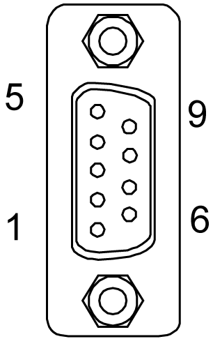
RS-232C
D-Sub 9 pin plug connector
|
Product side |
Pin No. |
RS-232C |
||
|---|---|---|---|---|
|
Signal Name |
Direction |
Meaning |
||
|
1 |
CD |
Input |
Carrier Detect |
|
|
2 |
RD (RXD) |
Input |
Receive Data |
|
|
3 |
SD (TXD) |
Output |
Send Data |
|
|
4 |
ER (DTR) |
Output |
Data Terminal Ready |
|
|
5 |
SG |
– |
Signal Ground |
|
|
6 |
DR (DSR) |
Input |
Data Set Ready |
|
|
7 |
RS (RTS) |
Output |
Request to Send |
|
|
8 |
CS (CTS) |
Input |
Send possible |
|
|
9 |
CI (RI)/VCC |
Input/– |
Called Status Display +5 Vdc ±5% Output 0.25 A*1*2 |
|
|
Shell |
FG |
– |
Functional Ground (Common with SG) |
|
*1 You can switch pin #9 between CI (RI) and VCC via the software. The VCC output is not protected against overcurrent. To prevent damage or malfunction, use only within the rated current.
*2 When using Open Box, use external equipment so that the sum of COM1 VCC output and COM2 VCC output totals 0.25 A.
Interfit bracket is #4-40 (UNC).
Recommendations:
-
Cable Connector: XM3D-0921 manufactured by OMRON Corporation.
-
Cable Cover: XM2S-0913 manufactured by OMRON Corporation.
-
Jack Screw (#4-40 UNC): XM2Z-0073 manufactured by OMRON Corporation.
RS-422/485
D-Sub 9 pin plug connector
|
Product side |
Pin No. |
RS-422/RS-485 |
||
|---|---|---|---|---|
|
Signal Name |
Direction |
Meaning |
||
|
1 |
RDA |
Input |
Receive Data A (+) |
|
|
2 |
RDB |
Input |
Receive Data B (-) |
|
|
3 |
SDA |
Output |
Send Data A (+) |
|
|
4 |
ERA |
Output |
Data Terminal Ready A (+) |
|
|
5 |
SG |
– |
Signal Ground |
|
|
6 |
CSB |
Input |
Send Possible B (-) |
|
|
7 |
SDB |
Output |
Send Data B (-) |
|
|
8 |
CSA |
Input |
Send possible A (+) |
|
|
9 |
ERB |
Output |
Data Terminal Ready B (-) |
|
|
Shell |
FG |
– |
Functional Ground (Common with SG) |
|
Interfit bracket is #4-40 (UNC).
Recommendations:
-
Cable Connector: XM3D-0921 manufactured by OMRON Corporation.
-
Cable Cover: XM2S-0913 manufactured by OMRON Corporation.
-
Jack Screw (#4-40 UNC): XM2Z-0073 manufactured by OMRON Corporation.