DIO Interface
DIO Connector
38 pin connector (Model number: CA7-DIOCN5-01)
Cable connection side:

|
Pin No. |
Signal name |
Pin No. |
Signal name |
|---|---|---|---|
|
A1 |
IN1 |
B1 |
IN0 (CT0)*1 |
|
A2 |
IN3 |
B2 |
IN2 (CT1)*1 |
|
A3 |
IN5 |
B3 |
IN4 (CT2)*1 |
|
A4 |
IN7 |
B4 |
IN6 (CT3)*1 |
|
A5 |
IN9 |
B5 |
IN8 |
|
A6 |
IN11 |
B6 |
IN10 |
|
A7 |
IN13 |
B7 |
IN12 |
|
A8 |
IN15 |
B8 |
IN14 |
|
A9 |
NC |
B9 |
COM |
|
A10 |
Sink: NC |
B10 |
Sink: +24 Vdc |
|
Source: +24 Vdc |
Source: +24 Vdc |
||
|
A11 |
Sink: 0 Vdc |
B11 |
Sink: 0 Vdc |
|
Source: NC |
Source: 0 Vdc |
||
|
A12 |
OUT1 |
B12 |
OUT0 |
|
A13 |
OUT3 |
B13 |
OUT2 |
|
A14 |
OUT5 |
B14 |
OUT4 |
|
A15 |
OUT7 |
B15 |
OUT6 |
|
A16 |
OUT9 |
B16 |
OUT8 |
|
A17 |
OUT11 |
B17 |
OUT10 |
|
A18 |
OUT13 |
B18 |
OUT12 |
|
A19 |
OUT15 |
B19 |
OUT14 |
*1 Signal names in parentheses () indicate the counter input used.
*2 Signal names in parentheses () indicate the pulse output or PWM output used.
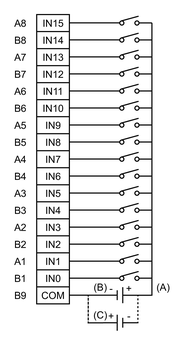
Digital Input Specifications
|
Input terminal |
IN0...IN15 |
||
|
Rated voltage |
24 Vdc |
||
|
Maximum allowable voltage |
28.8 Vdc |
||
|
Input type |
Sink/Source Input |
||
|
Rated current |
2.25 mA |
||
|
Input resistance |
10.7 kΩ |
||
|
Input points |
16 |
||
|
Common lines |
1 |
||
|
Common design |
16-point/1 common line |
||
|
Operation range |
ON voltage |
15...28.8 Vdc |
|
|
OFF voltage |
0...5 Vdc |
||
|
ON current |
2.25 mA |
||
|
OFF current |
1.0 mA or less |
||
|
Filtering |
Normal input |
0.5 ms x N (N is 0 to 40) |
|
|
High-speed counter |
None, 4 μs, or 40 μs |
||
|
Input signal display |
No LED indicators |
||
|
Status display |
None |
||
|
Isolation |
Yes |
||
|
External connection |
38 pin connector (used with Output section) |
||
|
Cable length |
Normal input |
Maximum 50 m (164 ft) |
|
|
High-speed counter/Pulse catch input |
Maximum 10 m (33 ft) |
||
Digital Output Specifications
|
Output terminal |
OUT0...OUT3 |
OUT4...OUT15 |
|
|
Rated voltage |
24 Vdc |
||
|
Rated voltage range |
20.4 Vdc...28.8 Vdc |
||
|
Output type |
PFXSTC6300TADDKE: Sink output |
||
|
Maximum load current |
0.3 A/point, total 3.2 A |
||
|
Minimum load current |
1 mA |
1 mA (Pulse/PWM output unavailable) |
|
|
Output voltage drop |
1.5 Vdc or less |
||
|
Output delay time |
OFF to ON |
5 µs or less |
50 µs or less |
|
ON to OFF |
5 µs or less |
50 µs or less |
|
|
Type of output |
Transistor output |
||
|
Common lines |
2 |
||
|
Common design |
8-point/ 1 common line x 2 |
||
|
External connection |
38 pin connector (used with Input section) |
||
|
Output protection type |
Output is unprotected |
||
|
Output points |
16 |
||
|
Output signal display |
No LED indicators |
||
|
Status display |
None |
||
|
Isolation |
Yes |
||
|
External power supply |
For Signal: 24 Vdc |
||
|
Cable length |
Normal output |
Maximum 150 m (492 ft) |
|
|
Pulse/PWM output |
Maximum 5 m (16 ft) |
||
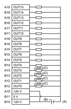
Output Circuit: Sink type

-
24 Vdc External power supply
-
Sink type
-
Dummy resistor*1
*1 (Example) If the output current is 24 Vdc 50 mA, the output delay time (OFF to ON) is 1.5 μs. If more responsiveness is required or the load is light, install an external dummy resistor to increase the amount of current.
Output Circuit: Source type

-
24 Vdc External power supply
-
Source type
-
Dummy resistor*1
*1 (Example) If the output current is 24 Vdc 50 mA, the output delay time (OFF to ON) is 1.5 μs. If more responsiveness is required or the load is light, install an external dummy resistor to increase the amount of current.
High-Speed Counter/Pulse Catch Input Specifications
DIO standard input can be used as a high-speed counter or a pulse catch input. For setup information, refer to your screen editing software manual.
High-Speed Counter
Pulse Catch Input
Pulse/PWM Output Specifications
DIO standard output can be used as a pulse or PWM output. For setup information, refer to your screen editing software manual.
Pulse Output
|
Output points |
4 |
|
Output method |
PLS0...PLS3 (OUT0...OUT3)*1 |
|
Load voltage |
24 Vdc |
|
Maximum load current |
50 mA/1-point |
|
Minimum load current |
1 mA |
|
Maximum output frequency |
Up to 65 kHz/1-point*1 |
|
Pulse acceleration/ |
Available |
|
ON duty |
50% ±10% (at 65 kHz)*2 |
*1 Set with the software.
*2 ON duty error (10%) is reduced if the output frequency is low.
PWM Output
|
Output points |
4 |
|
Output method |
PWM0...PWM3 (OUT0...OUT3)*1 |
|
Load voltage |
24 Vdc |
|
Maximum load current |
50 mA/1-point |
|
Minimum load current |
1 mA |
|
Maximum output frequency |
Up to 65 kHz/1-point*1 |
|
ON duty |
19...81% (at 65 kHz)*2 |
*1 Set with the software.
*2 ON duty (effective range) is wider if the output frequency is low.


