Installation Procedure on DIN Rail and Panel
This section describes how to install the rear module on a DIN rail and the display module to the panel.
 DANGER DANGER
|
|---|
|
HAZARD OF ELECTRIC SHOCK, EXPLOSION,
OR ARC FLASH
Failure to follow these instructions will result in death or serious injury.
|
| NOTICE |
|---|
|
EQUIPMENT DAMAGE
Always use the installation
gasket.
Failure to follow these instructions can result in equipment damage.
|
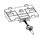
- Connect the separation cable to the rear module installation
adapter. Affix the screws on both sides of the cable connector to
secure the cable to the adapter.
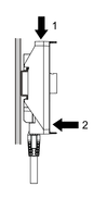
- Position the top groove of the rear module installation
adapter on the top edge of the DIN rail.NOTE: Install the adapter on a DIN rail compatible with IEC 60715 TH35-7.5.

- Push down on the adapter until the bottom groove of the
installation adapter fits under the DIN rail.
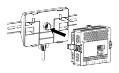
- Insert and push the rear module straight in to the adapter,
until they lock into place.
- Place the display module on a clean and level surface with the screen facing down.
- Check that the gasket is seated securely into the bezel
groove, which runs around the perimeter of the display panel frame.NOTE: Always use the installation gasket, since it absorbs vibration in addition to repelling water. For the procedure on replacing the installation gasket, refer to Replacing the Installation Gasket.
- Based on this product's Panel Cut Dimensions, open a mount-hole on the panel.
- Insert the display module and the anti-rotation tee into
the panel hole from the front side. Use the socket wrench to tighten
the nut. The necessary torque for the nut is 1.2 to 2.0 N•m (10.62 to 17.70 lb-in).NOTE:
-
The anti-rotation tee is used to install the display module horizontally on the panel. When you do not use an anti-rotation tee, applying 2.5 N•m (22.12 lb-in) or more force to the display module could cause the product to rotate. By using an anti-rotation tee, 6 N•m (53.10 lb-in) or more force could cause the product to rotate.
-
If the panel thickness does not meet the specified conditions, use the spacer (sold separately).
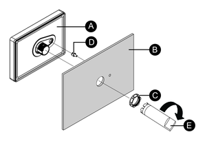
-
Display module
-
Panel
-
Installation nut
-
Anti-rotation tee
-
Socket wrench
-
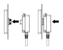
- Insert and push the separation cable straight in to the
display module, until they lock into place.