
RS-422/485 isolated x 2
Specifications
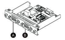
By factory default, the RS-485 interface is connected on the interface cartridge. Depending on your requirements, you can change the interface to a RS-422 interface included with the product.
-
After attaching to the unit, right side
-
After attaching to the unit, left side
-
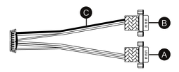
Red wire
RS-485 interface cable
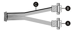
RS-422 interface cable
| Asynchronous transmission | RS-422 (isolated) x 2, RS-485 (isolated) x 2 |
| Data length | 7 or 8 bits |
| Stop bit | 1 or 2 bits |
| Parity | None, odd or even |
| Flow control | xon/xoff control |
| Data transmission speed | 2,400...115,200 bps |
| Connector | D-Sub 9 pin (plug) |
| Power consumption (max.) | 0.58 W |
The serial interface is isolated. The SG (signal ground) and FG (frame ground) terminals are not connected inside this product. When the serial interface connector is D-Sub, connect the FG wire to the shell.
 DANGER DANGER
|
|---|
|
ELECTRIC SHOCK AND FIRE
When using the SG terminal to connect an external
device to this product:
Failure to follow these instructions will result in death or serious injury.
|
 CAUTION CAUTION
|
|---|
|
LOSS OF COMMUNICATION
Failure to follow these instructions can result in injury or equipment damage.
|
| NOTICE |
|---|
|
BROKEN ENCLOSURE
Do not exert more torque than the amount specified.
Failure to follow these instructions can result in equipment damage.
|
Pin Assignment
RS-422: D-Sub 9 pin plug connector
Module side:

| Pin No. | RS-422 | ||
|---|---|---|---|
| Signal name | Direction | Description | |
| 1 | TxD- | Output | Send data – |
| 2 | TxD+ | Output | Send data + |
| 3 | RxD- | Input | Receive data – |
| 4 | RxD+ | Input | Receive data + |
| 5 | SG | — | Signal ground (isolated) |
| 6 | NC | — | No connection |
| 7 | NC | — | No connection |
| 8 | NC | — | No connection |
| 9 | NC | — | No connection |
| Shell | FG | — | Frame ground |
RS-485: D-Sub 9 pin plug connector
Module side:
| Pin No. | RS-485 | ||
|---|---|---|---|
| Signal name | Direction | Description | |
| 1 | Data– | Input/Output | Communication data – |
| 2 | Data+ | Input/Output | Communication data + |
| 3 | NC | — | No connection |
| 4 | NC | — | No connection |
| 5 | SG | — | Signal ground (isolated) |
| 6 | NC | — | No connection |
| 7 | NC | — | No connection |
| 8 | NC | — | No connection |
| 9 | NC | — | No connection |
| Shell | FG | — | Frame ground |
For both RS-422 and RS-485:
Recommended jack screw is #4-40 (UNC).
Replacing with RS-422
- Use a box wrench (5 mm) to remove the screws on the interface.
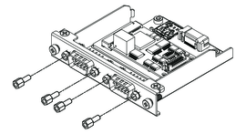
- Disconnect the interface connector from the cartridge, and also disconnect the cable connected to the board.
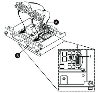
- As shown below, attach the cable connector so that the
cable’s red wire is at position 1. Attach so that the port
with the red wire is on side B.NOTE: For a RS-485 connection, attach the cable connector so that the red wire is at position 2.
-
Red wire
-
- Insert the RS-422 interface connector into the cartridge and tighten the screws.NOTE: The necessary torque is 0.3 N•m (2.7 lb-in).
Termination Resistor Setting
Termination resistor setting is necessary when using RS-422/485 isolated x 2. Set up by referring to the following table.

| Dip SW | OFF | ON | Port |
|---|---|---|---|
| 1 | Normal | Termination | For RS-422 (port identified with a red wire) |
| 2 | Normal | Termination | For RS-422 (port not identified with a red wire) |
| 3 | Normal | Termination | For RS-485 (port identified with a red wire) |
| 4 | Normal | Termination | For RS-485 (port not identified with a red wire) |