
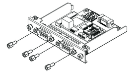
Replacing with RS-422
- Use a box wrench (5 mm) to remove the screws on the interface.
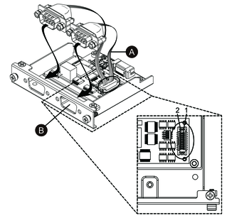
- Disconnect the interface connector from the cartridge, and also disconnect the cable connected to the board.
- As shown below, attach the cable connector so that the
cable’s red wire is at position 1. Attach so that the port
with the red wire is on side B.NOTE: For a RS-485 connection, attach the cable connector so that the red wire is at position 2.
-
Red wire
-
- Insert the RS-422 interface connector into the cartridge and tighten the screws.NOTE: The necessary torque is 0.3 N•m (2.7 lb-in).
Termination Resistor Setting
Termination resistor setting is necessary when using RS-422/485 isolated x 2. Set up by referring to the following table.

| Dip SW | OFF | ON | Port |
|---|---|---|---|
| 1 | Normal | Termination | For RS-422 (port identified with a red wire) |
| 2 | Normal | Termination | For RS-422 (port not identified with a red wire) |
| 3 | Normal | Termination | For RS-485 (port identified with a red wire) |
| 4 | Normal | Termination | For RS-485 (port not identified with a red wire) |