A.2.2.2 Word Type - #H System Variables
#H_AlarmSyncStatus
The processing status of alarm analysis is stored. The corresponding bit is turned ON according to the processing status.
When the analysis operation is canceled, all the bits in the system variable #H_AlarmSyncStatus are turned OFF.
|
Bit
|
Description
|
Details
|
|
0
|
Analyzing operation
|
Analyzing operation
(This bit is ON from the time [START] is touched on the search condition input keyboard, to the time the state where the analysis information is maintained is released.)
|
|
1
|
Search in progress
|
During search processing of the information corresponding to the condition
(This bit is ON from the time [START] is touched on the search condition input keyboard, to the time the analysis list screen is displayed.)
|
|
2
|
Undisplayed data present
|
Data not displayed in the analysis data is present (data exceeds 500)
|
|
3
|
Unable to display past data
|
Past data display for the historical trend graph is not set
|
|
4
|
External storage not connected
|
External storage is not connected to the display unit
|
|
5
|
External storage not formatted
|
The external storage is not connected properly
|
|
6
|
File read error
|
CSV files for the operation log are damaged.
|
|
7
|
File format error
|
CSV files for the operation log are not correct.
|
|
8
|
Saving of the operation log is in progress
|
Since saving of the CSV for the operation log function is executed, the search processing is stopped
|
|
9
|
Window display error
|
Unable to perform analysis because the search menu or the search condition input keyboard is being displayed with other functions, or because all windows are being used.
|
|
10...15
|
Reserved
|
-
|

-
When bit 8 or bit 9 is turned ON, the subsequent processing is not performed. Even if each of bits 0 to 7 are turned ON, analysis processing is continued.
#H_BackLightColor
Changes the display color of the backlight.
This operates only on models that support changing the backlight.
 1.5 Supported Features
When you write "0", it is amber and "1" is red. Do not set other colors.
To change the backlight color on GP-4100 series (Monochrome Model), please use the following values.
The backlight colors are different from one model to the next.
1.5.1.1 For Those Using GP-4100 Series
00h: Color as set up in the Base screen's [Screen Attribute]
01h: Green or white
02h: Red
03h: Orange or pink
11h: Green or white (Blink)
12h: Red (Blink)
13h: Orange or pink (Blink)
Other values: Green or white
#H_ChangeScreenNo
Specify the Screen Number of the Change-to Destination.
When the communication method is Direct Access, it is stored in LS0008, and when the method is the Memory Link Method, it is stored in 0015.
#H_CounterbySecond
Increments the elapsed time once every second immediately after the power is turned ON, and is stored in Bin format to LS2035.
#H_CsvIndex_Control
Create an index file for the recipe (CSV data) during RUN and store it in the external storage.
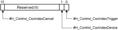
When #H_Control_CsvIndexTrigger is turned ON, start creating an index file in an external storage.
-
While #H_Control_CsvIndexCancel is ON, an index file will not be created even if #H_Control_CsvIndexTrigger is turned ON.
Specify a location to save an index file. Specify the same save location as a recipe (CSV data).
-
0: CF card (or SD card)
-
1: USB Storage
When #H_Control_CsvIndexCancel is turned ON during the index file creation, the creation process will be cancelled. The index file being created will be deleted.

-
Do not turn off the power of the display unit while creating an index file. It may not only stop the index file creation process but it may damage the data saved in the external storage.
-
To use #H_CsvIndex_Control, select the [Transfer CSV Data] setting in the [Transfer CSV Data (Condition)] tab. #H_CsvIndex_Control will not operate if [Transfer CSV Data] is disabled.
For details regarding the Common Settings [Transfer CSV Data (Condition)], please refer to the following.
26.8.1 Transfer CSV Data (Condition)
-
If an index file is created using the system variable, the display unit's performance deteriorates as the number of CSV files for index file increases. If you don't want to deteriorate the display unit's performance, create an index file in offline mode or in GP-Pro EX.
-
During the CSV data transfer, an index file cannot be generated. To use the index file creation, make sure that the transfer start bit of the CSV data transfer is OFF.
-
When starting the transfer of CSV data, if "no external storage" or "CF card error" occur, index file creation processing will not run. Turn OFF the transfer start bit of the Transfer CSV Data.
-
During the index file creation, CSV data transfer is not permitted.
-
If the following actions are taken during the index file creation, the creation process will be cancelled.
-
Going to offline mode
-
Run screen transfer
-
Remove a USB storage device
-
If the index file is already saved, it will be overwritten when the creation of a new index file is completed.
-
During the index file creation, change to the values of "#H_Control_CsvIndexTrigger" and "#H_Control_CsvIndexDevice" are disabled and the creation process continues.
#H_CsvIndex_Counter
The total number of CSV files subjected to the index file will be stored.
#H_CsvIndex_Status
The process status of the index file creation will be stored.
|
0000h
|
Before creating an index file
|
|
0001h
|
Creating an index file
|
|
0002h
|
Complete the index file creation successfully
|
|
0010h
|
#H_Control_CsvIndexCancel is turned ON and the index file creation is interrupted.
|
|
0100h
|
The external storage device is not inserted to the display unit or not formatted properly.
|
|
0200h
|
No CSV files are stored in the external storage device or the data in the CSV file is invalid.
|
|
0400h
|
No space in the external storage device or data cannot be overwritten since the index file is read-only.
|
-
When ending normally, turning OFF #H_Control_CsvIndexTrigger clears to zero the value stored in #H_CsvIndex_Statusstart.
-
When #H_Control_CsvIndexCancel is turned OFF, #H_Control_CsvIndexTrigger is automatically turned OFF. The value stored in #H_CsvIndex_Status is also cleared to zero.
#H_CsvIndex_Total
The total number of CSV files that are stored in the external storage device at the index file creation will be stored.
#H_CurrentBrightness
Stores the current value for the brightness (0:Bright...100:Dark) set up on the display unit (display screen).
-
The following lists models compatible with dimmer settings and brightness ranges you can set up.
1.5 Supported Features
#H_CurrentDay
The "Date" of the date information is stored in BCD format in LS2050.
#H_CurrentDayofTheWeek
The current value for the day is stored in LS9310. The day is calculated from the Year, Month, and Day of the display unit's onboard IC (RTC) clock.
A.1.1.4 LS9000 Area (Direct Access Method)
#H_CurrentHour
The "Hour" of the time information is stored in BCD format in LS2051.
#H_CurrentMinute
The "Minute" of the time information is stored in BCD format in LS2052.
#H_CurrentMonth
The "Month" of the date information is stored in BCD format in LS2049.
#H_CurrentScreenNo
Stores the screen number being displayed.
When the communication method is Direct Access, it is stored in LS0000, and when the method is the Memory Link Method, it is stored in 0015.
#H_CurrentSecond
The "Seconds" of the time information is stored in BCD format in LS2053.
#H_CurrentTokenSpeed
Used only during a Serial Multilink connection.
The current value of the time taken for one transfer cycle of a token packet (a Command Right for PLC) through multiple connected Displays. The unit is 10 milliseconds. The data is updated every time the maximum value is changed or when the screen is changed. The data's initial value is "0". There is an error of +/-10 ms. Stored in LS2041.
#H_CurrentYear
The "Year" of the date information is stored in BCD format in LS2048.
The stored value is the last 2 digits of year.
#H_DispScanCounter
The counter increments each time the Part set on the display screen processes.
The value is updated when all processing for the target Parts has finished and is stored in Bin format to LS2038.
#H_DispScanTime
The display time starts from the first Part set on the display screen to the end of the last Part.
Data is stored to LS2036 in Bin format, in millisecond units. The data is updated when all processing for the target Parts has finished. The data's initial value is 0, and there is an error of +/- 10 milliseconds.
#H_EtherLink_ConstCommuniMemInfo
Can be used only for Master display unit.
Stores the total value of the Continuous Communication Amount of the Master/Slave/GP-Viewer EX stations. For computing the number of addresses, refer to the following.
7.6.2 Procedure - How to Calculate the Communication Traffic
#H_EtherLink_ConstItemCount
Can be used only for Master display unit.
The total value of the Continuous Communication Amount actually requested by the Master/Slave/GP-Viewer EX from the Master display unit is stored in bytes. 16-bit, 32-bit, and bit addresses are calculated as 2 bytes, 4 bytes, and 2 bytes, respectively.
#H_Expression_Err_Status
Stores the operation error status of the animation function or Data Display operation.
The #H_Expression_BCD_Err, #H_Expression_Division_Err, and #H_Expression_Overflow error statuses are stored in Bit 0, Bit 1, and Bit 2, respectively. For more details, please refer to the following.
A.2.2.1 Bit Type - #H System Variables
#H_FileManager_PageScrollCount
You can set the number of pages to scroll when the change page button is touched. For example, if the value 5 is set and the change page button (Next) is touched, the fifth next page is displayed. When 0 is set, the number of pages to change is 1.
#H_From_Year/ #H_From_Month/ #H_From_Day/ #H_From_Hour/ #H_From_Minute/ #H_From_Second
Data for "year" (last 2 digits of the year), "month", "day" "hour", "minute", and "second" for the From field of the search condition input keyboard are stored.
20.10.3 Entering Search Conditions
-
This feature cannot run on models that do not support the Refine Search/Sort function.
#H_GlobalWindowControl
The Global Window is displayed when bit 0 of LS0016 is turned ON, and is hidden when the bit is turned OFF.
When bit 1 of LS0016 is turned ON, the display order of the Global Window can be changed.
#H_GlobalWindowNo
The indirectly selected Global Window registration number is stored in LS0017.
Stored values are in Bin or BCD format and range from 1 to 2000.
#H_GlobalWindowPosX
The indirectly selected X coordinate display position in the top left corner of the Global Window is stored in LS0018.
Values are in Bin or BCD format.
#H_GlobalWindowPosY
The indirectly selected Y coordinate display position in the top left corner of the Global Window is stored in LS0019.
Values are in Bin or BCD format.
#H_GW_AverageInterruptTime
This is a GP-4G01 system variable. You can use this variable when the [Use Gateway Mode] check box is selected.
Turn ON #H_GW_AnalyzeModeFlag to check the current system communication delay. GP-4G01 receives 1 byte from the current system host, then the GP-4G01 sends that single byte one hundred times to the communication device to get the average delay time written to this system variable. Units are in milliseconds (ms).
On the positive transition of #H_GW_AnalyzeModeFlag, the value of #H_GW_AverageInterruputTime is reset to zero.
#H_GW_DivideInterruptSize
This is a GP-4G01 system variable. You can use this variable when the [Use Gateway Mode] check box is selected.
Input Range: 1...65535
Use to adjust the communication volume between the GP-4G01 and device/PLC. The larger the value, the more data is processed by GP-4G01 at a time, which may delay communication in existing systems. The smaller the value data is run with smaller blocks of data, which reduces the impact on communication of existing systems.
When you want to check how changes to #H_GW_DivideInterruptSize affect operations, after changing its value set #H_GW_AnalyzeModeFlag ON. While #H_GW_AnalyzeModeFlag is ON, even if there is a change in value of #H_GW_DivideInterruptSize it is not reflected in operations.
#H_GW_InterruptFrequency
This is a GP-4G01 system variable. You can use this variable when the [Use Gateway Mode] check box is selected.
Input Range: 1...100
Used to define the communication frequency, you can use this variable to adjust the communication speed with the device/PLC. Increase the value so that communication by the GP-4G01 itself, or communication via GP-4G01, takes priority over existing system communications. Decrease the value so existing system communication takes priority.
When you want to check how changes to #H_GW_InterruptFrequency affect operations, after changing its value set #H_GW_AnalyzeModeFlag ON. While #H_GW_AnalyzeModeFlag is ON, even if there is a change in value of #H_GW_InterruptFrequency it is not reflected in operations.
#H_GW_MaximumInterruptTime
This is a GP-4G01 system variable. You can use this variable when the [Use Gateway Mode] check box is selected.
Turn ON #H_GW_AnalyzeModeFlag to check the current system communication delay. GP-4G01 receives 1 byte from the current system host, then the maximum delay time to send to the communication device is written to this system variable. Units are in milliseconds (ms).
When #H_GW_AnalyzeModeFlag is ON, the value of #H_GW_MaximumInterruputTime is reset to zero.
#H_HistoricalTrendMagnification
The status of Zoom In/Out Display for the Historical Trend Graph is stored. A value is stored in this system variable when zoom in/zoom out is executed, and when a Historical Trend Graph with the [Default Magnification] set is displayed by Screen Change or Window Display.
0: Thin Out Mode
1: Original Size
2: 2 Times
4: 4 Times
8: 8 Times
-
When multiple Historical Trend Graphs are displayed, the Display Magnification for the last Historical Trend Graph for which you used zoom in or zoom out is stored.
-
When a Historical Trend Graph without the [Default Magnification] set is displayed as a result of a Screen Change or Window Display, the value in the system variable may not match with the Display Magnification of the Historical Trend Graph on display.
#H_JpegCaptureFileNo
When the "Save In" location is any location other than [FTP server], the file number for the screen capture to be obtained is specified as LS2074.
You can use this field when the [Auto Increment File Number] check box is selected. From the [System Settings], click [Display Unit] and in the [Mode] tab see the [Screen Capture] area.
#H_LocalName
Stores the name of the display unit.
In the [Video/Movie] settings, select the [Save to CF/USB] check box and for the [User Set String] select the [Indirect] option. You can copy the station name to the address configured in the [User Set String], and then when the [Control Address] is set ON, use the station name as the destination folder name.
When saving videos from multiple Displays, you can easily determine which folder is for which Display.
28.10.1 Video / Movie Settings Guide
#H_LockElapsedTime
In the [System Settings] node's [Display Unit], when [Enable Operation Lock] is set up on the [Extended Settings] page's [Operation Lock] area, this variable stores the elapsed time (in seconds) from the start of operation lock.
#H_LockRemainderTime
In the [System Settings] node's [Display Unit], when [Timeout] is set up in the [Extended Settings] page's [Operation Lock] area, this variable stores the time remaining (in seconds) until operation lock is unlocked.
#H_LockOwnerIPAddr
Obtains the IP address of the display unit acting as the Operation Lock.
-
If the display unit for the source Lock has multiple LAN ports as shown below, the IP address of any one of the multiple Ethernet settings is stored. Therefore, an IP address different from the actual IP address used to communicate with may be stored.
-
When using models with more than one LAN port
-
When using the EZ LAN Adapter with models that have one LAN port
-
To check which models support EZ LAN Adapter, refer to the following.
1.5 Supported Features
#H_LoginUserID
Stores the User ID of persons currently logged in.
#H_MachineNo
When using a GP3000H conversion adapter (model: AGP3000H-ADPCOM-01) with a hand-held GP, periodically saves the ID number (unit number) of the conversion adapter. With this feature, you can check if the conversion adapter is connected to the hand-held GP.
After the power is turned ON, until the model number of the conversion adapter is read, the value is 0.
To enable, below the [System Settings] node click [Display Unit]. In the [Mode] tab, enable [Conversion Adapter]. You can also enable or disable the conversion adapter in Offline Mode.
Refer to the Maintenance/Troubleshooting Guide for Offline Mode configuration details.
#H_MAXTokenSpeed
Used only during a Serial Multilink connection.
The current value of the time taken for one transfer cycle of a token packet (a Command Right for PLC) through multiple connected Displays. Each unit is 10 milliseconds. The data is updated every time the maximum value is changed or when the screen is changed. The data's initial value is "0". There is an error of +/-10 ms. Stored in LS2040.
#H_NumpadInputMode
Switch the input mode for the EZ numeric keypad.
By writing the following value, you can change the input mode of the numeric keypad.
|
Value (Dec)
|
Description
|
Details
|
|
0
|
Use tenkey
|
Always operates as a numeric keypad. Can be used only when the Data Display is in the input wait state.
Does not operate even when the function key is set.
|
|
1
|
Use function keys
|
Always operates as function keys.
Cannot be used as a numeric keypad.
|
|
2
|
Use tenkey and function keys
|
The display unit will automatically switch between the numeric keypad input and function key input.
It will switch to the numeric keypad input only when the Data Display is in the input wait state.
|
-
When you write a value other than 0 to 2, the tenkey pad does not operate.
#H_PrxFileName
Displays the project file name.
The project file name, including extension, can display up to 256 single or double-byte characters.
-
Even if you change the file name in Explorer or other method, if the project is not saved, the changed file name is not reflected in #H_PrxFileName. However, if you check the value of #H_PrxFileName in simulation, the latest project file name is displayed.
-
Even if you change the value in #H_PrxFileName, the actual project file name does not change.
#H_PrxFileNameLanguage
Defines the language of the project file name stored in the #H_PrxFileName system variable.
|
Value (Dec)
|
Language
|
|
0
|
ASCII
|
|
1
|
Japanese
|
|
2
|
Chinese (Traditional)
|
|
3
|
Chinese (Simplified)
|
|
4
|
Korean
|
|
5
|
Russian (Cyrillic)
|
|
6
|
Thai
|
-
Match the settings of #H_PrxFileNameLanguage with the project file name in #H_PrxFileName.
#H_RecipeGroupID
The Group ID for the enhanced recipe is specified. It is used when transferring/receiving and importing/exporting the enhanced recipe data.
-
The values for this system variable become the Group ID to be displayed on the enhanced recipe list.
#H_RecipeGroupName
The Group Name for the enhanced recipe is stored.
-
When the #H_RecipeGroupID value is invalid or is 0, 0 is stored in #H_RecipeGroupName.
#H_RecipeID
The Recipe ID for the enhanced recipe is specified. It is used when transferring/receiving the enhanced recipe data.
-
The Recipe ID for the enhanced recipe that imports/exports the enhanced recipe data as a CSV file is specified.
-
The Recipe ID for the recipe label that is selected in the enhanced recipe list is stored.
-
The Recipe ID for the element data belonging to the displayed enhanced recipe data list is specified.
-
The values for this system variable become the Recipe ID to be displayed on the enhanced recipe list.
#H_RecipeLabel
Stores up to 32 single or double-byte characters of the recipe label name selected in the Enhanced Recipe List (#H_RecipeGroupID, #H_RecipeID). The recipe label is stored using the character code defined in the enhanced recipe group's [Language] setting.
If there are two or more label languages, stores with the character code defined in [Select label language].
For information on recipe label character codes, refer to the following.
26.26 Confirming Which Enhanced Recipe's data is Transferred
#H_RecipeLabelSortType
The display order for the recipe label to be displayed on the enhanced recipe list is specified.
0: Recipe ID order
1: Recipe label (ascending order)
2: Recipe label (descending order)
#H_RecipeMatchedCount
16-bit integer variable that stores enhanced recipe search hits from the system variable #H_RecipeControlSearch. When no matching enhanced recipes are found, stores [0].
-
For models that support the Refine Search / Sort function, refer to the following.
1.5 Supported Features
-
Specify the search string in #H_RecipeSearchTarget.
-
Search results from the enhanced recipe list part are not reflected in this system variable.
#H_RecipeMatchedID[0]..[63]
16-bit integer array variable that stores enhanced recipe search results from the system variable #H_RecipeControlSearch. Stores up to 64 enhanced recipe IDs that match the search string.
When a number of enhanced recipes are found in a search result, the recipe IDs are stored from#H_RecipeMatchedID[0] in ascending order. When the search results in 65 or more recipes, the results of the 65th and subsequent recipes are discarded.
When no matching enhanced recipes are found, the value of #H_RecipeMatchedID[xx] is not updated and the previous data remains.
-
For models that support the Refine Search / Sort function, refer to the following.
1.5 Supported Features
-
#H_RecipeMatchedID[xx] cannot be used in logic programs.
-
Search results from the enhanced recipe list part are not reflected in this system variable.
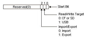
#H_RecipeProcessing
16-bit variable that stores the status of enhanced recipe operations such as transfer and edit. Each bit shows the progress and completion state of operations.
|
Bit
|
Description
|
Details
|
|
0
|
Transferring bit
|
The transfer status from the display unit to the connecting device is stored
|
|
1
|
Transfer Complete Flag
|
|
2
|
Receiving bit
|
The transfer status from the connecting device to the display unit is stored
|
|
3
|
Receiving Completion Flag
|
|
4
|
Exporting bit
|
The CSV output status to the external storage is stored
|
|
5
|
Export Completion Flag
|
|
6
|
Importing bit
|
The import status from the external storage is stored
|
|
7
|
Import Completion Flag
|
|
8
|
Updating bit of the enhanced recipe list
|
The update status of the enhanced recipe list is stored
|
|
9
|
Copying bit of the enhanced recipe list
|
The processing status of editing, copying, and deleting the recipe label is stored
|
|
10
|
Deleting bit of the enhanced recipe list
|
|
11
|
Editing bit of the enhanced recipe list
|
|
12
|
Reloading bit of the enhanced recipe list
|
The update status of the enhanced recipe data list is stored
|
|
13
|
Saving bit of the enhanced recipe list
|
The save status of the results by which the element values are edited is stored
|
|
14
|
Saving mapped address
|
Turns ON when writing the value of mapped addresses to element values, and turns OFF when the process is complete.
|
|
15
|
Saving mapped address complete
|
Turns ON when writing the value of mapped addresses to element values is complete.
|
#H_RecipeResultCopy
#H_RecipeControlCopy 16-bit integer variable that stores the status of the enhanced recipe copy operation.

-
Bit 1: Copy complete
Turns ON when the enhanced recipe copy operation is complete. When the copy control system variable #H_RecipeControlCopy turns OFF, #H_RecipeResultCopy also turns OFF.
-
Bit 0, 2...15: Reserved
Do not use.
#H_RecipeResultCSV
This 16-bit integer variable stores the processing results for importing/exporting enhanced recipe data as a CSV file.

|
Error Code
|
Description
|
Details
|
|
0
|
Completed successfully
|
|
|
1
|
Incorrect #H_RecipeGroupID value
|
Change the recipe group ID configured in the CSV file.
The recipe group ID is duplicated, out of range, or not set.
|
|
2
|
Incorrect #H_RecipeID value
|
Change the recipe ID configured in the CSV file.
The recipe ID is duplicated, out of range, or not set.
|
|
3
|
Import unsuccessful
|
CSV file format discrepancy
|
|
4
|
Import unsuccessful
|
Absence of CSV files to be replaced
|
|
5
|
Import unsuccessful
|
Insufficient number of columns for CSV file format
|
|
6
|
Import unsuccessful
|
Excessive number of columns for CSV file format
|
|
7
|
Import unsuccessful
|
Excessive number of rows for CSV file format
|
|
8
|
Import unsuccessful
|
Excessive number of element value characters (character string is too long), or invalid characters mixed in.
|
|
9
|
Import unsuccessful
|
Values other than the character string of the element values are invalid (exceed the set range)
|
|
10
|
Import stopped
|
Importing interrupted because enhanced recipe element values are being edited.
|
|
11
|
Absence of files to be imported
|
Files for importing cannot be found. External storage, used as the save in location of files to import, may not be connected
|
|
12
|
Generation of export files unsuccessful
|
Files for exporting could not be generated. The probable causes are as follows:
|
|
13
|
Write Error
|
Write unsuccessful. Try to import or export again.
|
|
14
|
Write Error
|
|
15
|
Insufficient capacity
|
Cannot update due to insufficient space in the screen area
|
|
16
|
Reserved
|
-
|
|
17
|
Import unsuccessful
|
The label's language code is invalid. In the CSV file, the language code listed as the Label Language is incorrect. Alternatively, the label language in the CSV file and the current recipe label's language code are different.
|
|
18
|
Import unsuccessful
|
The language code of the text data is invalid. In the CSV file, the language code listed as the Data Language is incorrect. Alternatively, the data language in the CSV file and the current recipe group's language code are different.
|
|
19
|
Import unsuccessful
|
The CSV file has an undefined recipe label.
|
|
20
|
Import unsuccessful
|
The CSV file has an undefined element label.
|
-
During export and import, when #H_Control_USBDetachTrigger and #H_Control_SDDetachTrigger are turned ON, errors for either 3 to 9 or 12 are stored.
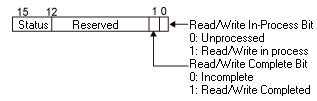
#H_RecipeResultSearch
This 16-bit integer variable stores the processing status of the enhanced recipe search.
-
Bit 0: Searching
This variable turns ON when running the enhanced recipe search and turns OFF when the search is complete.
-
Bit 1: Search complete
When the enhanced recipe search is complete, this variable turns ON. When the search control system variable#H_RecipeControlSearch turns OFF, #H_RecipeResultSearch also turns OFF.
#H_RecipeResultTransfer
Transfer processing results for the enhanced recipe data are stored.

|
Error Code
|
Description
|
Details
|
|
0
|
Completed successfully
|
|
|
1
|
Incorrect #H_RecipeGroupID value
|
The specified enhanced recipe group does not exist or is out of range.
|
|
2
|
Incorrect #H_RecipeID value
|
The specified enhanced recipe does not exist or is out of range.
|
|
3
|
Device access error
|
During transfer/receive, access to the device failed.
|
|
4
|
Incorrect element value
|
Receive process canceled. Values outside the setting range are included as element values.
|
|
5
|
Failed to update element value
|
Receive process canceled as element values are being edited. You can check the edit status of element values with #H_RecipeStatusEdit.
|
|
6
|
Failed to update element value
|
Receive process canceled as element values included invalid characters.
|
|
7
|
Failed to update element value
|
Unable to save mapped address values to element values as the recipe was either saving or receiving.
|
|
8
|
Incorrect security level
|
Access is not allowed because the recipe's security level is higher than the current login security level. Please login with a security level at or above the recipe security level.
|
|
9...12
|
Reserved
|
|
|
13
|
Write Error
|
Write unsuccessful. Transfer again.
|
|
14
|
Write Error
|
Write unsuccessful. Transfer again.
|
|
15
|
Insufficient capacity
|
Cannot update due to insufficient space in the screen area
|
#H_RecipeSearchOption
This 16-bit integer variable specifies enhanced recipe search options. Set up before searching.
Applies to search operations with an enhanced recipe list part and with the system variable #H_RecipeControlSearch.
-
Bit 0: Distinguish upper and lower case characters
When ON, upper and lower case letters in a search string are not distinguished in the search operation. When OFF, distinguishes the difference between upper and lower case letters in search strings.
#H_RecipeSearchTarget
System variable used to specify the search string for enhanced recipes. Enter the enhanced recipe label to search for in this system variable and use #H_RecipeControlSearch to start the search.
Using this system variable you can specify up to 64 bytes of continuous data, up to 64 single-byte or 32 double-byte characters.
You can use the following wildcards in the search string.
-
*: Any text
Example: When you specify "Recipe*" in #H_RecipeSearchTarget
Search results include Recipe A, Recipe AB, Recipe ABC, and so on.
-
?: Any one character
Example: When you specify "Recipe??" in #H_RecipeSearchTarget
Search results include RecipeAB, RecipeXX, and so on. In this case, RecipeA has fewer letters than the search condition, and RecipeABC has more, so these do not appear in the search results.
-
For models that support the Refine Search / Sort function, refer to the following.
1.5 Supported Features
-
When there are two or more label languages, the search is applied to the current language. When specifying your search text, use character codes that match the recipe label language.
For information about each language's character codes, see "Language code" in the following topic.
26.20.2 Enhanced Recipe - CSV File Format
#H_RemoteHMI_Connect_Status
Stores the Pro-face Remote HMI client and server (display unit) connection status.
When [Allow multiple client connections] is enabled, stores [3] if both synchronous and asynchronous clients connect, and stores [1] if only synchronous clients connect.
|
Value (Dec)
|
Description
|
|
0
|
Client and server (display unit) are not connected
|
|
1
|
Connecting in synchronous mode
|
|
2
|
Connecting in asynchronous mode
|
|
3
|
Connecting in synchronous/asynchronous mode
|
-
This system variable is not supported by the Pro-face Remote HMI Server (application).
#H_RemoteHMI_DisconnectMode
Available when Pro-face Remote HMI is enabled.
Stores the amount of time from when the client connection cannot be confirmed, until communication is disconnected and touch operation is canceled.
For example, when 5 seconds is set and a communication failure occurs and on the client a momentary switch is ON, 5 seconds after the connection cannot be confirmed touch operation is canceled (OFF).
|
Value (Dec)
|
Description
|
|
0
|
Standard time out (approximately 30 seconds)
|
|
2...5
|
Timeout after defined number of seconds
|
-
If the value changes while the client is connected, communication is interrupted for a moment and then reconnected.
-
When the set value is out of range, operates using the standard time out (approximately 30 seconds).
-
If power is turned off or the display unit is restarted, the system variable is initialized with the value configured in the [Disconnect after communication is down for (#H_RemoteHMI_DisconnectMode)] field, available from [Main Unit], [Remote Viewer], [Pro-face Remote HMI].
-
If you set to any value other than 0, confirm operation in the actual run-time environment.
If you set to any value other than 0, even though the connection may not be broken, due to unintended timing it may become disconnected. If that happens, adjust the value.
#H_RemoteHMI_Touch_Status
Stores the status of monopolize touch on the Pro-face Remote HMI.
|
Value (Dec)
|
Description
|
|
0
|
Touch operation is not monopolized
|
|
1
|
Touch operations possible only on the server side
|
|
2
|
Touch operations possible only on the client side
|
#H_SecurityBackupControl
Imports or exports security data.
Write the operation type (import/export) in bit 2, and the location to save security data in bit 1.
When bit 0 turns ON, the operation set in bit 2 and 1 is processed.
The exported security data is saved in the [Security] folder of the external storage specified as the location to save, with the file name [SecFPDat.bin].
When you import security data from the [Security] folder of the specified external storage, the file name should also be [SecFPDat.bin].
You can import exported security data and security data created with the Fingerprint Recognition Setting Tool.
#H_SecurityBackupStatus
Stores the status when security data is imported/exported.
Status details
|
Bit 12 to 15
|
Description
|
Details
|
|
0
|
Completed successfully
|
Read/write is successfully completed
|
|
1
|
Level Mode Error
|
The password setting is set to the Level Mode. (The setting needs to be changed to the User ID Mode.)
|
|
2
|
Security Data Error
|
Incorrect security settings (User ID is duplicated or no User ID or Password is set.)
|
|
3
|
Reserved
|
-
|
|
4
|
No external storage
|
External storage is not available. Or, the CF card cover is open.
|
|
5...8
|
Reserved
|
-
|
|
9
|
Read/write error
|
Unsuccessful to read from/write to display unit or external storage
|
|
10...15
|
Reserved
|
-
|
When an error has occurred during security data import or export, the error status is stored.
-
The Reading/Writing bit turns OFF when the read/write operation is complete. Additionally, the Read Completion/Write Completion bit turns ON. By turning the #H_SecurityBackupControl start bit OFF, the completion bit also turns OFF.
-
When an error has occurred during reading/writing, the completion bit does not turn ON. The Reading/Writing bit turns OFF when an error has occurred and its error status is stored in #H_SecurityBackupStatus. The error status is not cleared when the #H_SecurityBackupControl start bit is turned OFF. It will be cleared next time the process is completed successfully.
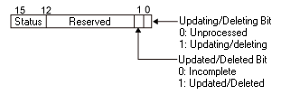
#H_SecurityFingerprintControl
Update or destroy the EZ fingerprint recognition unit database.
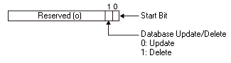
Set the operation type (update/discard) in bit 1. When bit 0 turns ON, the data base is updated or discarded.
Update the database when using a new EZ Fingerprint Recognition Unit. Also, update the database when using an EZ Fingerprint Recognition Unit which was used with other display unit.
#H_SecurityFingerprintStatus
Stores the error status, when an error has occurred during updating/discarding the EZ Fingerprint Recognition Unit's database.
Status details
|
Bit 12 to 15
|
Description
|
Details
|
|
0
|
Completed successfully
|
Occurs when the database has been updated/discarded successfully
|
|
1
|
EZ Fingerprint Recognition Unit Connection Error
|
Occurs when the EZ Fingerprint Recognition Unit is not connected
|
|
2
|
When fingerprint data does not exist
|
When security data does not exist in the specified folder during database update
|
|
3...15
|
Reserved
|
-
|
-
The Updating/Discarding bit turns OFF when the update/discard operation is complete. Additionally, the Update Completion/Discard Completion bit turns ON. By turning the #H_SecurityFingerprintControl start bit OFF, the completion bit also turns OFF.
-
When an error occurs while updating/discarding, the completion bit does not turn ON. The Updating/Discarding bit turns OFF, and the error status is stored in #H_SecurityFingerprintStatus. The status is not cleared when the #H_SecurityBackupControl start bit is turned OFF. It will be cleared next time the process is completed successfully.
#H_SecurityWriteControl
Stores the execution status and "Save in" location of online writing of passwords.
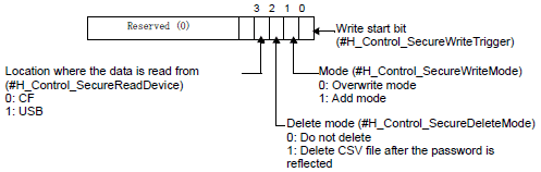
The password of the CSV file is reflected on the display unit by setting bit 0, OFF to ON.
When writing to the display unit, check the following items for Level Mode/User ID Mode and Write Mode.
O: Check Errors X: Do not check errors
|
Contents to be checked
|
Level Mode
|
User ID Mode
|
|
Overwrite
|
Append
|
Overwrite
|
Append
|
|
External storage is mounted on the body
|
O
|
O
|
O
|
O
|
|
CSV file has a designated path and file name.
|
O
|
O
|
O
|
O
|
|
CSV file is in a designated format.
|
O
|
O
|
O
|
O
|
|
Password data of the CSV file is free of the following error.
|
-
|
-
|
-
|
-
|
-
Password (including the level and user ID) is described using up to eight single-byte characters.
|
O
|
O
|
O
|
O
|
-
Password (including the level and user ID) does not include a space.
|
O
|
O
|
O
|
O
|
-
Level, password and user ID have no spaces (if they are described with spaces only, they are regarded as being deleted, instead of being an error).
|
X
|
X
|
O
|
O
|
-
Levels are within range, 1 to 15.
|
X
|
X
|
O
|
O
|
|
The number of set user IDs is not more than 100.*1
|
X
|
X
|
O
|
O
|
|
Level Mode /User ID Mode of the CSV file is consistent with that on the display unit.
|
O
|
O
|
O
|
O
|
|
User ID (password) is not duplicated.*2
|
O
|
O
|
O
|
O
|
The contents to be checked are different depending on Write Mode.
|
Overwrite
|
Check the number of settings in the file for writing.
|
|
Append
|
Check the sum of the number of settings in the data to write and the existing data.
|
|
Level Mode
|
Overwrite
|
Check that the password is not duplicated within the file for writing.
|
|
Append
|
Check if the password is not duplicated in the write file, and check if any passwords are duplicated between the write data and existing data.
|
|
User ID Mode
|
Overwrite
|
Check that the ID is not duplicated within the file for writing.
|
|
Append
|
Check if the ID is not duplicated in the write file, and check if any IDs are duplicated between the write data and existing data.
|
#H_SecurityWriteStatus
When an error has occurred during online writing of a password, the error status is stored.
Status details
|
Bit Combination
15 - 12
|
Description
|
Details
|
|
0000
|
Completed successfully
|
Writing to the display unit is successfully completed
|
|
0001
|
Reserved
|
|
|
0010
|
Reserved
|
|
|
0011
|
Reserved
|
|
|
0100
|
No external storage
|
When writing to the body, the external storage is not connected, or the CF Card cover is open
|
|
0101
|
Delete Error
|
Unsuccessful to delete the CSV file.
|
|
0110
|
Reserved
|
|
|
0111
|
Reserved
|
|
|
1000
|
User IDs out of range
|
The number of user IDs exceeded 100 when writing to the display unit.
|
|
1001
|
Write data error
|
Unsuccessful to write data to NAND.
|
|
1010
|
CSV file name or path error
|
CSV file does not have a designated path or file name.
|
|
1011
|
CSV file
Formatting error
|
CSV file is not in a designated format.
|
|
1100
|
CSV data error
|
There is an error in the password data.
|
|
1101
|
Mode error
|
evel Mode or User ID Mode does not match that on the display unit.
|
|
1110
|
Duplication error
|
Password is duplicated (Level PS Mode).
User ID is duplicated (User ID Mode).
|
-
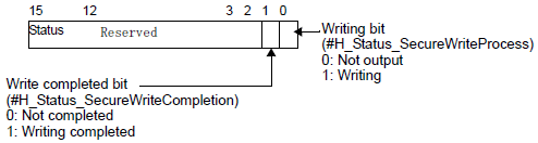
When writing is completed, the writing bit automatically turns OFF and the write completed bit turns ON at the same time.
When the user turns OFF the write start bit, the completed bit automatically turns OFF.
-
Even when you turn OFF the write start bit before the write completed bit turns ON, the write completed bit is automatically turned OFF.
-
When an error has occurred when writing, the completed bit does not turn ON. The writing bit turns OFF, and an error status is stored in HMI system variable #H_SecurityWriteStatus. Even if the write start bit is turned OFF, the status is not cleared automatically. It will be cleared next time the process is completed successfully.
#H_SetBrightness
Stores the set up value for the display unit (display screen) brightness. By using a data part to change the variable value, you can change the brightness.
Store values between 0 (bright) and 100 (dark).
-
The following lists models compatible with dimmer settings and brightness ranges you can set up.
1.5 Supported Features
#H_SetDay
The "Date" value of the date information is stored in BCD format in LS2058.
The stored value is 2 digits and ranges from 01 to 31. By rewriting this value using a data part, you can change the "Date" of the time data. However, out-of-range values cannot be stored.
#H_SetHour
The "Hour" value of the time information is stored in BCD format in LS2059.
The stored value is 2 digits and ranges from 00 to 23. By rewriting this value using a data part, you can change the "Hour" of the time data. However, out-of-range values cannot be stored.
#H_SetMinute
The "Minute" value of the time information is stored in BCD format in LS2060.
The stored value is 2 digits and ranges from 00 to 59. By rewriting this value using a data part, you can change the "Minutes" of the time data. However, out-of-range values cannot be stored.
#H_SetMonth
The "Month" value of the date information is stored in BCD format in LS2057.
The stored value is 2 digits and ranges from 01 to 12 (Month). By rewriting this value using a data part, you can change the "Month" of the time data. However, out-of-range values cannot be stored.
#H_SetSecond
The "Seconds" value of the time information is stored in BCD format in LS2061.
The stored value is 2 digits and ranges from 00 to 59 (Seconds). By rewriting this value using a data part, you can change the "Seconds" of the time data. However, out-of-range values cannot be stored.
#H_SetYear
The "Year" value of the date information is stored in BCD format in LS2056.
The stored value is the last 2 digits of year (00 to 99). By rewriting this value using a data part, you can change the "Year" of the time data. However, out-of-range values cannot be stored.
#H_SignalBuzzerHL_Control
Set the buzzer sound tone to be heard from the EZ tower light.
|
0000h
|
Default
|
|
0001h
|
High
|
|
0002h
|
Low
|
#H_SignalBuzzerHL_Status
Stores the processing status of the buzzer tone setting for the EZ Tower Light.
|
0000h
|
Disconnected
|
|
0001h
|
High
|
|
0002h
|
Low
|
#H_SignalBuzzerPattern_Control
Set the buzzer sound pattern to be heard from the EZ tower light.
|
0000h
|
Default
|
|
0001h
|
Buzzer OFF
|
|
0002h
|
Continuous (beep.......)
|
|
0003h
|
Intermittent (beep, beep, beep)
|
|
0004h
|
Intermittent 2 (beep/beep/beep/beep/beep/beep/beep/beep)
|
|
0005h
|
Intermittent tone 3 (5 short beeps, 5 short beeps)
|
#H_SignalBuzzerPattern_Status
Stores the processing status of the buzzer pattern setting from the EZ Tower Light.
|
0000h
|
Default
|
|
0001h
|
Buzzer OFF
|
|
0002h
|
Continuous (beep.......)
|
|
0003h
|
Intermittent (beep, beep, beep)
|
|
0004h
|
Intermittent 2 (beep/beep/beep/beep/beep/beep/beep/beep)
|
|
0005h
|
Intermittent tone 3 (5 short beeps, 5 short beeps)
|
#H_SignalBuzzerVolume_Control
Sets the buzzer volume for the EZ Tower Light.
|
0000h
|
Default
|
|
0001h
|
High
|
|
0002h
|
Medium
|
|
0003h
|
Low
|
#H_SignalBuzzerVolume_Status
Stores the processing status of the buzzer tone setting for the EZ Tower Light.
|
0000h
|
Disconnected
|
|
0001h
|
High
|
|
0002h
|
Medium
|
|
0003h
|
Low
|
#H_Signal**Blink_Control
Sets the lighting pattern for the EZ Tower Light.
|
0000h
|
Default
|
|
0001h
|
Does not illuminate
|
|
0002h
|
Normally lit
|
|
0003h
|
Turns On/Off every 500 ms (1 second cycle)
|
|
0004h
|
Turns On/Off every 250 ms (500 ms cycles)
|
-
Corresponding to below, the number in "**" indicates the bottom, middle or top of the EZ Tower Light:
01: Bottom
02: Middle
03: Top
#H_Signal**Blink_Status
Stores the lighting pattern for the EZ Tower Light.
|
0000h
|
Disconnected
|
|
0001h
|
Does not illuminate
|
|
0002h
|
Normally lit
|
|
0003h
|
Turns On/Off every 500 ms (1 second cycle)
|
|
0004h
|
Turns On/Off every 250 ms (500 ms cycles)
|
-
Corresponding to below, the number in "**" indicates the bottom, middle or top of the EZ Tower Light:
01: Bottom
02: Middle
03: Top
#H_Signal**Color_Control
Sets the lighting colors for the EZ Tower Light.
|
0000h
|
Default
|
|
0001h
|
Does not illuminate
|
|
0002h
|
Red
|
|
0003h
|
Green
|
|
0004h
|
Blue
|
|
0005h
|
Yellow
|
-
Corresponding to below, the number in "**" indicates the bottom, middle or top of the EZ Tower Light:
01: Bottom
02: Middle
03: Top
#H_Signal**Color_Status
Stores the setting status of lighting colors for the EZ Tower Light.
|
0000h
|
Default
|
|
0001h
|
Does not illuminate
|
|
0002h
|
Red
|
|
0003h
|
Green
|
|
0004h
|
Blue
|
|
0005h
|
Yellow
|
-
Corresponding to below, the number in "**" indicates the bottom, middle or top of the EZ Tower Light:
01: Bottom
02: Middle
03: Top
#H_TagConsistencyConfig
The action for the tag consistency check is set.
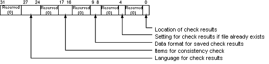
|
Bit
|
Description
|
|
0
|
Location of check results
ON: USB storage
OFF: SD card
|
|
4
|
Setting for check results if file already exists
ON: Do not overwrite
OFF: Overwrite
|
|
8...9
|
Date format for saved check results
00: yy/mm/dd
01: mm/dd/yy
10: dd/mm/yy
11: mm/dd
|
|
16...17
|
Items for consistency check
00 or 11: All the tags registered in the GP-Pro EX
01: Tags used in parts or common settings
|
|
24...27
|
Language for check results
0000: (ASCII) Europe and the United States
0001: Japanese
0010: Chinese (Traditional)
0011: Chinese (Simplified)
0100: Korean
0101: Russian (Cyrillic)
0110: Thai
Other than those above: Europe and the United States
|
-
For cases in which log file attributes are read-only, files cannot be overwritten even if bit 4 is turned OFF. Bit 10 for the consistency check status (#H_TagConsistencyStatus) is turned ON.
-
For cases in which Japanese is selected for the [Language] in the [Option Setting]GP-Pro EX [Option Setting], if languages other than Japanese are selected in bit 27 to 24, the error message is not displayed properly. Please set [Language] to English.
#H_TagConsistencyStatus
The processing status of tag consistency check is stored.
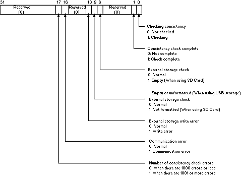
-
When #H_TagConsistencyTrigger (tag consistency check start) is turned OFF, bits for #H_TagConsistencyStatus are all turned OFF. However, during the consistency check, all the bits are turned OFF after the consistency check is completed (after bit 1 is turned ON).
-
If either bit 8 or 9 is turned ON, the consistency check is stopped.
-
Even if bit 10 is turned ON, the consistency check is continued.
#H_To_Year/ #H_To_Month/ #H_To_Day/ #H_To_Hour/ #H_To_Minute/ #H_To_Second
From the [To] field in the search condition's input keypad, stores the "year" (last 2 digits of the year), "month," "date," "hours," "minutes," and "seconds".
20.10.3 Entering Search Conditions
-
This feature cannot run on models that do not support the Refine Search/Sort function.
[PLC*]#H_DriverCycleTime
Stores the time from when the display unit requests data from the device/PLC, until the display unit receives the data in a unit of 1ms.
The name of the device obtaining the value is entered in [*]. Values for the device/PLC Communication Cycle Times 1 to 32 are stored in order in LS9400 to LS9431. The same applies to the following, with the values for PLC 2, 3, 4 stored in LS9432 to LS9527.
-
The device/PLC name is specified in the device/PLC settings.
-
H system variables store content from the 33rd item and beyond.
-
You can find the internal address that stores the communication cycle time from the [System Settings], [Peripheral List] page's [List of Device/PLC Management Addresses].
5.4.14 System Settings [Peripheral List] Settings Guide
[PLC*]#H_DriverCycleTime does not operate with the following devices/PLCs. Refer to the Pro-face website for the latest information.
http://www.pro-face.com/trans/en/manual/1081.html
|
Manufacturer Name
|
Driver
|
|
Digital Electronics Corporation of Japan
|
Memory Link
|
|
Generic SIO
|
|
General Ethernet
|
|
ODVA
|
EtherNet/IP Explicit Messaging*1
|
|
DeviceNet Slave
|
|
Schneider Electric SA
|
MODBUS Slave
|
|
YE Digital Corporation
|
MMCloud TCP Client
|
|
PROFIBUS International
|
PROFIBUS DP Slave
|
|
Cognex Corporation
|
In-Sight Vision Systems
|
|
CC-Link Partner Association
|
CC-Link Intelligent Device
|
|
CAN in Automation
|
CANopen Slave
|
|
SAE International
|
J1939
|
|
CRRC
|
Train Real Time Data Protocol
|
*1 This system variable does not operate if the [Enable Implicit Message] or [Enable Custom Explicit Message] check box is selected in the [Individual Device Settings] dialog box.
[PLC*]#H_DriverErrorCode
Stores any error code that has occurred. The name of the device obtaining the value is entered in [*].
To determine the error, check the value of the bottom 8 bits in the system variable. For example, with "RHxx006" the value "xx" is stored in the top 8 bits of the system variable and "006" is stored in the bottom 8 bits. To determine the last 3 digits of the error code, check the value of the bottom 8 bits in the system variable.
Please refer to the following for error codes.
T.7.1 Settings common to all Display models
[PLC*]#H_DriverErrorCount
Stores the number of errors that has occurred. The name of the device obtaining the value is entered in [*].
[PLC*]#H_DriverErrorDate
The elapsed time from Jan 1, 1970 00:00:00 until the date and time of error is stored in units of seconds. The date and time of error is based on the clock settings on the display unit.
The name of the device obtaining the value is entered in [*].
