A.2.2.1 Bit Type - #H System Variables
#H_Alarm_Trigger
This is a system variable that turns ON when an alarm, registered as alarm history, is triggered.
You can trigger this alarm to capture when processes such as screen change or data capture are run.
You can arbitrarily turn this system variable ON/OFF.
Once this system variable is turned ON, as long as it is not arbitrarily turned OFF, it remains ON until the display unit is turned OFF.
#H_Control_Buzzer
This is a system variable that controls display unit buzzers.
When the communication method is Direct Access, it is stored in bit 1 of LS0014, and when the method is the Memory Link Method, it is stored in bit 1 of 0011. This system variable turns ON during a buzzer output.

-
When #H_Control_BuzzerEnable is ON, the buzzer will not sound even when this system variable is ON.
-
With the SP5000 Series (excluding Standard Box), from System Settings [Display Unit] - [Operation] - [External Buzzer Output] even if you select [System Error Sound] and turn the system variable ON, there is no output to the external buzzer terminal.
#H_Control_BuzzerEnable
This is a system variable that controls the display unit buzzer function.
When the communication method is Direct Access, it is stored in bit 4 of LS0014, and when the method is the Memory Link Method, it is stored in bit 4 of 0011. When this system variable is OFF, buzzer output is enabled.
#H_Control_CsvIndexTrigger
The system variable to start creating an index file for the recipe (CSV data)
#H_Control_CsvIndexDevice
This is a system variable that displays a location of the saved index file. Specify the same save location as a recipe (CSV data).
#H_Control_CsvIndexCancel
This is a system variable that cancels to create an index file.
#H_Control_HardcopyPrint
This is a system variable used to print the display unit screen. When the communication method is Direct Access, it is stored in bit 2 of LS0014, and when the method is the Memory Link Method, it is stored in bit 2 of 0011. When the bit of this system variable is turned ON, the screen on the display unit begins printing.
#H_Control_JpegCaptureEnable
This is a system variable that controls the saving of display unit screens by Pro-Server EX. When the bit of this system variable is turned ON, display unit screens can be saved using Pro-Server EX.
#H_Control_JpegCaptureTrigger
This is a system variable that saves the screens that are being displayed on the display unit. When the bit of this system variable is turned ON, the screen on the display unit is saved as a JPEG.
Set up file save settings in the [Save in] options. From the [System Settings] node click [Display Unit], and in the [Mode] tab note the [Screen Capture] area.
 5.4.4.2 Display Unit [Mode] - Screen Capture
#H_Control_PLCmonopoly
Turns ON when there is a PLC monopoly during a Serial Multilink connection. It is stored in bit 7 of LS0014.
#H_Control_PrintCancel
This system variable cancels printing operations of the printer connected to the display unit. When the communication method is Direct Access, it is stored in bit 11 of LS0014, and when the method is the Memory Link Method, it is stored in bit 11 of 0011. When the bit of this system variable is turned ON, all printing processes set for display unit are canceled.
#H_Control_SDDetachTrigger
This is a system variable that is used when removing an SD card from the display unit. When this system variable is turned ON, #H_Status_SDUsing is turned OFF, and the SD card can be removed from the display unit.
For the removal method, please refer to the following.
5.3 Remove an External Storage Device
-
When this system variable is turned ON while writing the data from the SD card, #H_Status_SDUsing is not turned OFF until data writing is complete.
-
Please turn this system variable ON for 200 milliseconds or more.
#H_Control_SecureWriteTrigger
This is a system variable used when starting a writing operation of security data.
For writing security data, refer to the following.
#H_SecurityWriteControl
#H_Control_SecureWriteMode
This is a system variable used for selecting the write mode for security data.
For writing security data, refer to the following.
#H_SecurityWriteControl
#H_Control_SecureDeleteMode
This is a system variable that selects the delete mode for security data.
For writing security data, refer to the following.
#H_SecurityWriteControl
#H_Control_SecureReadDevice
This is a system variable used for selecting the read destination for security data.
For writing security data, refer to the following.
#H_SecurityWriteControl
#H_Control_StopAlarmSave
System variable for saving alarm history.
With the GP-4100 series (excluding GP-411*T3), if you turn off the display unit in the middle of saving historical data, all the data may be lost or you may not be able to save the data anymore.
Turning ON this bit before turning off the display unit enables you to save history data without the [Storage Frequency] (available from the [Common Settings] menu's [Alarm] command) triggering an automatic save operation.
When save is complete, #H_Status_AlarmSave turns ON.
#H_Control_USBDetachTrigger
This is a system variable that is used when removing a USB storage device from the display unit. When this system variable is turned ON, #H_Status_USBUsing is turned OFF and the USB storage device can be removed from the display unit.
For the removal method, please refer to the following.
5.3 Remove an External Storage Device
-
When this system variable is turned ON while writing the data from the USB storage device, #H_Status_USBUsing does not turn OFF until data writing is complete.
#H_DeviceMonitor
This is a system variable that displays the status of a device monitor. When the bit of this system variable is turned ON, the device monitor will start up.
#H_Expression_BCD_Err
Turns ON when a "BCD error" occurs while performing animation or Data Display operations.
#H_Expression_Division_Err
Turns ON when a "Zero division error" occurs while performing animation or Data Display operations.
#H_Expression_Overflow
When operating animations, performs "Curving" when storing data "with 64-bit signs" as "with 32-bit signs". This system variable turns ON when that Curving occurs.
-
If the range for data "with 64-bit signs" is exceeded during operation, occurrences of Curving cannot be detected.
#H_GW_AnalyzeModeFlag
This is a GP-4G01 system variable. You can use this variable when the [Use Gateway Mode] check box is selected.
This is a system variable that starts communication adjustment of GP-4G01 and the existing system.
As the value of #H_GW_AnalyzeModeFlag changes, each system variable operates as shown below.
|
#H_GW_AnalyzeModeFlag
|
Operation of each System Variable
|
|
When ON
|
Loads the values of #H_GW_DivideInterruptSize and #H_GW_InterruptFrequency .
|
|
Writes zero to #H_GW_AverageInterruptTime and #H_GW_MaximumInterruptTime.
|
|
While ON
|
The average delay time between the host device and device/PLC is written to #H_GW_AverageInterruptTime.
|
|
The maximum delay time between the host device and device/PLC is written to #H_GW_MaximumInterruptTime.
|
-
The values of #H_GW_DivideInterruptSize and #H_GW_InterruptFrequency affect display unit operations on the positive transition of #H_GW_AnalyzeModeFlag. While #H_GW_AnalyzeModeFlag is ON or while OFF, even if there is a change in value of #H_GW_DivideInterruptSize or #H_GW_InterruptFrequency, it is not reflected in operations.
-
You can use #H_GW_SaveConfigTrigger to save the values of #H_GW_DivideInterruptSize and #H_GW_InterruptFrequency to the display unit's project data. If you restart the display unit without saving, values set up in GP-Pro EX will be used.
-
You can use #H_GW_SaveConfigTrigger to run the save process when #H_GW_AnalyzeModeFlag is OFF.
#H_GW_SaveConfigCompletion
This is a GP-4G01 system variable. You can use this variable when the [Use Gateway Mode] check box is selected.
This variable turns ON after the save process triggered by the #H_GW_SaveConfigTrigger variable is complete.
This system variable does not turn OFF automatically. After confirming it turned ON, turn it OFF.
#H_GW_SaveConfigTrigger
This is a GP-4G01 system variable. You can use this variable when the [Use Gateway Mode] check box is selected.
Turning ON this variable saves the following system variable values to the display unit's project data. You can check if the save process is complete with #H_GW_SaveConfigCompletion.
-
The save operation does not run while #H_GW_AnalyzeModeFlag is ON. Turn #H_GW_AnalyzeModeFlag OFF before running the save process.

-
Do not turn off the display unit while saving. It may damage the internal memory content.
#H_IsAutoUnlockTimerMoved
This is a system variable that displays the operation state of the Auto Unlock Timer for Operation Lock.
Not operating.
Operating.
#H_IsLockedState
This is a system variable that displays the Operation Lock status of the display unit or GP-Viewer EX.
In a system with Ethernet Multilink, GP-Viewer and so on, where multiple equipment can run operations, use Operation Lock to disable operation from multiple equipment once an operation begins.
When the display unit (or GP-Viewer EX) is in use and operation from other equipment is disabled, or in other words Operation Lock is enabled preventing operation from other equipment, the bit of this system variable turns ON.
For information about Operation Lock, please refer to the following.
7.7 Preventing Operations from Other Display Units (Ethernet Multilink)
37.3.2 Starting GP-Pro EX to Creating Project Files - GP-Viewer EX
10.15.4.1 Special Switch - Switch Features
#H_IsLockOwner
This is a system variable that displays the Operation Lock status of the display unit or GP-Viewer EX.
In a system with Ethernet Multilink, GP-Viewer and so on, where multiple equipment can run operations, use Operation Lock to disable operation from multiple equipment once an operation begins.
When the display unit (or GP-Viewer EX) is in use and operation from other equipment is disabled, or in other words Operation Lock is enabled preventing operation from other equipment, the bit of this system variable turns ON.
For information about Operation Lock, please refer to the following.
7.7 Preventing Operations from Other Display Units (Ethernet Multilink)
37.3.2 Starting GP-Pro EX to Creating Project Files - GP-Viewer EX
10.15.4.1 Special Switch - Switch Features
#H_IsMasterDispUnit
This is a system variable that displays the station status of the display unit during an Ethernet Multilink connection. Turns ON for the Master station of Ethernet Multilink.
#H_IsSlaveDispUnit
This is a system variable that displays the station status of the display unit during an Ethernet Multilink connection. Turns ON for the Slave station of Ethernet Multilink.
#H_LadderMonitor
This is a system variable that starts the Ladder Monitor. It is stored in bit 1 of LS2078. When the bit of this system variable is turned ON, the Ladder Monitor will start up.
#H_LadderMonitorCache
This is a system variable that starts the Ladder Monitor. It is stored in bit 3 of LS2078. When the bit for this system variable is turned ON, the Ladder Monitor starts and the ladder programs cached in the CF card/SD card are displayed.
#H_OffBit
Turns OFF when the display unit starts up.
The value changes depending on the display unit only at startup. When used as an Always OFF bit, do not write to the bit address.
#H_OnBit
Turns ON when the display unit starts up.
The value changes depending on the display unit only at startup. When used as an Always ON bit, do not write to the bit address.
#H_RecipeControlCopy
Creates a copy of an Enhanced Recipe.
-
Before copying, set the Enhanced Recipe Group you want to edit in #H_RecipeGroupID.
When copying Enhanced Recipes, set the ID of the Enhanced Recipe to copy in #H_RecipeID.#H_RecipeControlCopy Turn ON this variable to start copying the Enhanced Recipe. You cannot cancel the operation once started.
This system variable is not turned OFF automatically.#H_RecipeResultCopy Use this variable to check the copy operation is complete, and then turn the variable OFF.
-
After copy is complete, the newly created Enhanced Recipe ID is stored in #H_RecipeID.
-
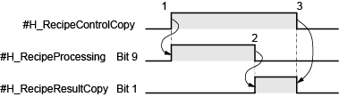
Turning on #H_RecipeControlCopy starts the copy operation and #H_RecipeProcessing's bit 9 turns ON.
-
When the process is complete, #H_RecipeProcessing's bit 9 turns OFF and #H_RecipeResultCopy's bit 1 turns ON.
-
Confirm #H_RecipeResultCopy's bit 1 is ON, and then turn OFF #H_RecipeControlCopy. #H_RecipeControlCopy, #H_RecipeResultCopy's bit 1 also turns OFF.
#H_RecipeControlCSVExport
Save the enhanced recipe data specified in #H_RecipeGroupID to an external storage as a CSV file.
The processing status is stored in #H_RecipeProcessing, and the processing results are stored in #H_RecipeResultCSV.
#H_RecipeControlCSVImport
The enhanced recipe data (CSV file) specified in #H_RecipeGroupID inside the external storage is read to the display unit.
The processing status is stored in #H_RecipeProcessing, and the processing results are stored in #H_RecipeResultCSV.
#H_RecipeControlMapAddress
Stores the Mapped Address value as an Enhanced Recipe element value.
When you turn ON this variable, you overwrite the element value of the enhanced recipe data with the value of the mapped address. The operation is performed on the enhanced recipe selected on the display unit. You cannot cancel a save in progress.
This system variable is not turned OFF automatically. Confirm with #H_RecipeProcessing that the update is complete, and then turn OFF the variable.
-
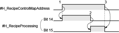
Turn ON #H_RecipeControlMapAddress to start writing the mapped address value to the element value, then #H_RecipeProcessing bit 14 turns ON.
-
When the write operation is complete, #H_RecipeProcessing bit 14 turns OFF and bit 15 turns ON.
-
Confirm #H_RecipeProcessing bit 15 is ON, and then turn OFF #H_RecipeControlMapAddress.#H_RecipeControlMapAddress, #H_RecipeProcessing bit 15 also turns OFF.
#H_RecipeControlReload
Loads the enhanced recipe element value from the display unit's project data.
Turn ON #H_RecipeControlReload to read the current enhanced recipe from the display unit's project data.
-
Use this system variable to cancel changes to element values on the display unit.
#H_RecipeControlSave
Saves the Enhanced Recipe.
-
Run save after making changes to element values on the display unit. If you do not save, edited values are overwritten when reloading the Enhanced Recipe or selecting other Enhanced Recipes.
Turn ON #H_RecipeControlSave to save the selected enhanced recipe's element value.
This system variable is not turned OFF automatically. Use #H_RecipeProcessing bit 13 to confirm save is complete, then turn OFF the variable.
#H_RecipeControlSearch
System variable that starts searching Enhanced Recipes.
Turn ON to start searching recipes in the enhanced recipe group selected in #H_RecipeGroupID. You cannot cancel a search once started. Before you start a search, specify the target enhanced recipe label in #H_RecipeSearchTarget, and the search options in #H_RecipeSearchOption.
#H_RecipeControlSearch does not turn OFF automatically. Confirm with #H_RecipeResultSearch that the search is complete, and then turn OFF the variable.
-
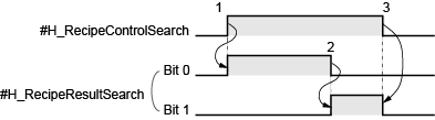
Turn ON #H_RecipeControlSearch to start the search, then #H_RecipeResultSearch bit 0 turns ON.
-
When the search process ends, #H_RecipeResultSearch bit 0 turns OFF and bit 1 turns ON.
-
Confirm that #H_RecipeResultSearch bit 1 is ON, and then turn OFF #H_RecipeControlSearch.#H_RecipeControlSearch, #H_RecipeResultSearch bit 1 turns OFF.
-
This system variable is for the Refine Search / Sort function only.
For models that support the Refine Search / Sort function, refer to the following.
1.5 Supported Features
-
You can display search results on an Enhanced Recipe List. To display results, in the Enhanced Recipe List enable [Refine Search / Sort].
#H_RecipeControlSend
The enhanced recipe data specified in #H_RecipeGroupID and #H_RecipeID is transferred from the display unit to a connecting device. The processing status is stored in #H_RecipeProcessing, and the processing results are stored in #H_RecipeResultTransfer.
When the following is performed during transfer, processing is stopped, and the error status is stored in #H_RecipeResultTransfer.
For more details on the transfer method, please refer to the following:
26.19.2 Transfer - Creating and Transferring Enhanced Recipe Data
#H_RecipeControlUpload
Data is read from the connecting device and imported to the display unit as the enhanced recipe data specified in #H_RecipeGroupID and #H_RecipeID. The processing status is stored in #H_RecipeProcessing, and the processing results are stored in #H_RecipeResultTransfer.
When the following is performed during transfer, processing is stopped, and the error status is stored in #H_RecipeResultTransfer.
For more details on the transfer method, please refer to the following:
26.19.2 Transfer - Creating and Transferring Enhanced Recipe Data
#H_RecipeStatusEdit
When the element value reaches the edit state in the enhanced recipe data list, it is turned ON.
While it is turned ON, importing and exporting of the enhanced recipe data cannot be performed.
#H_RemoteHMI_DisableConnections
System variable for terminating connections between Pro-face Remote HMI clients and the server.
|
Value
|
Description
|
|
ON
|
While ON, clients cannot connect to the server. If this system variable turns ON while clients are connected to the server, the connection is terminated.
|
|
OFF
|
Clients can connect to the server.
|
-
This system variable turns OFF when returning from offline mode or after a screen transfer. In offline mode, the value does not change from when you entered offline mode.
#H_Reset
This is a system variable that restarts the display unit. When the bit of this system variable is turned ON, the display unit restarts.
#H_Status_AlarmSave
For the GP-4100 series (excluding GP-411*T3), when #H_Control_StopAlarmSave is ON and the alarm history save operation is complete, this system variable bit turns ON. Resetting #H_Control_StopAlarmSave OFF turns this system variable OFF.
#H_Status_DispOnOff
This is a system variable that displays the screen display state of the display unit.
When the communication method is Direct Access, it is stored in bit 9 of LS0006, and when the method is the Memory Link Method, it is stored in bit 9 of 0001. This system variable turns ON when the display unit screen is OFF.
#H_Status_HistoricalTrend
This system variable indicates the mode of Display Historical Data for the Historical Trend Graph. It turns ON when the Historical Trend Graph in the display switches to the Display Historical Data mode. It turns OFF when the Historical Trend Graph exits the Display Historical Data mode.
#H_Status_JpegCaptureCompletion
This is a system variable that displays the save status of the screen being displayed on the display unit. This system variable turns ON after a GP screen is saved.
#H_Status_JpegCaptureProcess
This is a system variable that displays the save status of the screen being displayed on the display unit. This system variable turns ON while a GP screen is being saved.
#H_Status_PLCmonopoly
Turns ON when another Display has a PLC monopoly during a Serial Multilink connection. It is stored in bit 7 of LS0006.
#H_Status_Print
This is a system variable that displays the print status of the display unit. This system variable turns ON during a printing operation for the following function. When the communication method is Direct Access, it is stored in bit 2 of LS0006, and when the method is the Memory Link Method, it is stored in bit 2 of 0001.
-
Screen Hard Copy
-
Banner Alarm
-
Alarm History (Real-time, Batch Print)
-
Sampling (Real-time, Batch Print)
-
CSV display function (Partial Printing, Print All)
#H_Status_SDUsing
This is a system variable that displays the connection status of the SD card connected to the display unit.
One of the following states.
The SD card is not connected to the display unit.
-
Even if the SD card is physically connected to the display unit, if this system variable is turned OFF, access to the SD card is disabled. Remove the SD card and re-insert it.
-
Do not perform any of the following actions while writing data to the SD card. This may result in incomplete files remaining in the SD card, or damage to the SD card.
-
Moving to offline mode
-
Screen Transfer to the Display Unit (Send Project)
-
Removing the SD card
#H_Status_SecureWriteProcess
This is a system variable that displays the write status for security data. This system variable turns ON when security data is being written.
#H_Status_SecureWriteCompletion
This is a system variable that displays the write status for security data. This system variable turns ON when after security data has been written.
#H_Status_USBUsing
This is a system variable that displays the connection status of a USB storage device connected to the display unit.
One of the following states.
The USB storage device is connected to the display unit.
-
Even if the USB storage device is physically connected to the display unit, if this system variable is turned OFF, access to the USB storage device is disabled. Remove the USB storage device and insert again.
-
Do not perform any of the following actions while writing data to the USB storage device. This may result in an incomplete file or damage to the USB storage device.
-
Going to offline mode
-
Screen Transfer to the Display Unit (Send Project)
-
Remove a USB storage device
#H_Status_WindowInterlock
This is a system variable to display a Window's display status set in the [Disable Touch Features Except for Window].
This system variable will be turned ON when the Window set in the [Disable Touch Features Except for Window] is displayed.
If a new window without the [Disable Touch Features Except for Window] setting is displayed while this system variable is ON, the bit remains ON. If you close all the Windows with the [Disable Touch Features Except for Window] settings, the bit will be turned OFF.
#H_TagConsistencyTrigger
It is turned ON when starting the check for tag consistency.
For the consistency check operation, please refer to the following.
7.8.2 Checking tag consistency
-
This system variable is not turned OFF automatically. After verifying that the consistency check completion bit for #H_TagConsistencyStatus is turned ON, turn it OFF manually.
#H_TagConsistencyCheckCancel
It is turned ON when stopping the check for tag consistency.
-
This system variable is not turned OFF automatically. After verifying that the consistency check completion bit for #H_TagConsistencyStatus is turned ON, turn it OFF manually.
#H_TransferChange
This system variable turns ON when the display unit restarts after transfer of project files is completed.
You can use it as a script trigger condition.
Once this system variable is turned ON, as long as it is not arbitrarily turned OFF, it remains ON until the display unit is turned OFF.
[PLC*]#H_ErrorStatus
This is a system variable to check the status of communication errors with the device/PLC.
The communication status is normal.
There is an error in the communication status.
[PLC*]#H_ScanOffStatus
This is a system variable that displays the status of communication scans of the device/PLC. The bit of this system variable will turn ON if a communication scan is stopped by the communication scan control ([PLC*]#H_ScanOffControl).
The values from 1 to 32 devices of [Device/PLC1] are transferred to each bit of LS9560 to LS9561, in sequence. Similarly, the values of [Device/PLC 2] are stored in LS9562 to LS9563, the values of [Device/PLC 3] are stored in LS9564 to LS9565, and the values of [Device/PLC 4] are stored in LS9566 to LS9567.
-
H system variables store content from the 33rd item and beyond.
[PLC*]#H_ScanOffControl
This is a system variable that controls the communication scans of the device/PLC. Communication scans will stop when the bit of this system variable is turned ON.
The values from 1 to 32 devices of [Device/PLC1] are transferred to each bit of LS9550 to LS9551, in sequence. Similarly, the values of [Device/PLC 2] are stored in LS9552 to LS9553, the values of [Device/PLC 3] are stored in LS9554 to LS9555, and the values of [Device/PLC 4] are stored in LS9556 to LS9557.
-
H system variables store content from the 33rd item and beyond.
-
You can find the internal device address that stores ON/OFF status of communication scans from the addresses listed in the [System Settings], [Peripheral List] page's [List of Device/PLC Management Addresses].
5.4.14 System Settings [Peripheral List] Settings Guide
