PCI/PCIe Card Installation
When using the Advanced Box with PCI/PCIe slots attached, you can install commercially available PCI add-on cards or PCI Express add-on cards (PCI/PCIe cards). You can install PCI/PCIe cards with the following configuration.
| Slot 1 | Slot 2 | |
|---|---|---|
| PCI x 1 + PCIe x 1 | PCI | PCIe |
| PCIe x 2 | PCIe1 | PCIe2 |
| PCI x 2 | PCI1 | PCI2 |
NOTE: The total power consumption of PCI/PCIe cards can be up to 12 W, regardless of whether
one or two cards are installed.
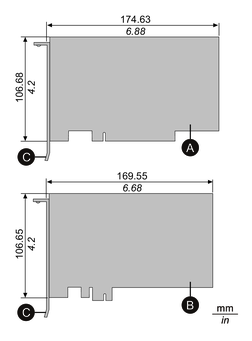
PCI/PCIe card dimensions
The maximum size of PCI/PCIe cards that can be installed are as follows.
-
PCI add-on card (short length)
-
PCI Express add-on card (half length)
-
I/O bracket
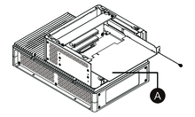
Installation procedure
 DANGER DANGER |
|---|
|
HAZARD OF ELECTRIC SHOCK, EXPLOSION,
OR ARC FLASH
Failure to follow these instructions will result in death or serious injury.
|
| NOTICE |
|---|
|
ELECTROSTATIC
DISCHARGE
Take the necessary protective measures
against electrostatic discharge before attempting to remove the cover.
Failure to follow these instructions can result in equipment damage.
|
| NOTICE |
|---|
|
BROKEN ENCLOSURE
Do not exert more torque than the amount specified.
Failure to follow these instructions can result in equipment damage.
|
- Disconnect the power supply from the Box Module.
- Touch the housing or ground connection (not the power supply) to discharge any electrostatic charge from your body.
- Remove the screws (4 pieces) of the PCI/PCIe slot cover.

- Slide the cover in the direction of the arrow on the top
of the cover, and remove it.

- Remove the screw from the interface cover, then remove
the cover.

- Insert the PCI/PCIe card, and secure the card with the screw removed in step 5.
- Replace the PCI/PCIe slot cover and tighten the screws.