
Attaching USB Cable Clamp
When using a USB device, attach a USB cable clamp to the USB interface to prevent the USB cable from being disconnected.
 WARNING WARNING |
|---|
|
EXPLOSION
HAZARD
Failure to follow these instructions can result in death, serious injury, or equipment
damage.
|
NOTE: Watch your fingers. The edge
of the clip is sharp.
- For USB Type A,
mount the clip to the USB mark
 on the USB connector shell so that it overlaps. For USB Type C, you can mount it
to either
side of the connector. For both USB Type A and USB Type C, the clip matches a length
of 27 to 43.5 mm (1.06 to 1.71 in) for the USB cable connector.
on the USB connector shell so that it overlaps. For USB Type C, you can mount it
to either
side of the connector. For both USB Type A and USB Type C, the clip matches a length
of 27 to 43.5 mm (1.06 to 1.71 in) for the USB cable connector.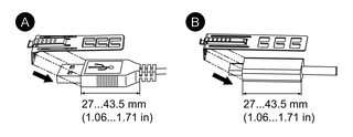
-
USB Type A
-
USB Type C
-
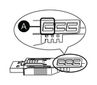
- Align the clip and the USB cable connector shell. Adjust
the position of the holes where the clip is attached. To ensure stability,
select the clip-hole position that is closest to the base of the connector
shell.
-
Pass the tie through here.
-
- As shown, pass the tie through the clip hole. Next, turn
the tie and pass it through the head so that the USB cable can pass
through the center of the tie loop. The clip is now attached to the
USB cable.NOTE:
-
Check the direction of the head beforehand. Make sure the USB cable is through the center of the tie loop and that the tie can pass through the head.
-
You can substitute the tie provided with PFXZCCLUSA or PFXYP6CLUSC, or other commercially available ties with a width of 4.8 mm (0.19 in) and thickness of 1.3 mm (0.05 in).

-
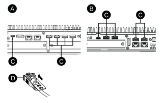
- While pressing the grip on the clip, insert the cable from step 3 all the way into
the USB
host interface. Make sure that the tab of the clip is secured to the
USB cable attached to this product.NOTE: As shown in the figure below, the location of the notch for USB ports is different between the Advanced Box and Standard Box. Confirm the location of the notch, and insert the tab of the clip.
-
Advanced Box
-
Standard Box
-
Notch
-
USB interface
-