|
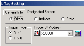
| Selecting both [Direct] of [Designated Screen] and Trigger Type [0 → 1] or [1 → 0] |
| |
| In case that Trigger Type is [0 → 1], the picturtes on Base Screen / Image Screen will be displayed when the Bit Address is ON. In case of [1 → 0], the pictures on Base Screen / Image Screen will be displayed when the Bit Address is OFF. |
 |
| |
 |
Is Bit Address correct? |
|
| |
|
| |
Being connected to PLC or Temperature Controller |
| |
Please check that [Trigger Bit Address] of L Tag and Bit Address of PLC are matched. |
| |
|
| |
Being connected to Board Computer with Memory Link Type. |
| |
Please check that [Trigger Bit Address] of L Tag and the Description transfered from HOST are matched. |
| |
|
| |
|
 |
Please set Bit Address ON/OFF by PLC by force. |
|
| |
|
| |
Being connected to PLC or Temperature Controller |
| |
Please STOP the program of PLC and change Bit Address of PLC with Ladder Software by force. Please confirm the Display of GP at that time. |
| |
|
| |
Being connected to Board Computer with Memory Link Type. |
| |
Please STOP the program of HOST and change only Bit Address by force. Please confirm the Display of GP at that time. |
| |
|
| |
|
 |
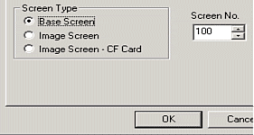
Please check Screen Number and Screen Type which you would like to call. |
|
| |
|
| |
Please check the Screen Number which you have designated on L Tag excists.
At the same time, it is possible to designate [Base Screen] or [Image Screen] on [Screen Type]. |
| |
 |
| |
|
| |
|
 |
Please check Display Location. |
|
| |
Please check whether the objects which you would like to display are located on the center point of the screen.
The center point of the screen which you would like to display is neccesary to match on the coodinate of L Tag. |
| |
|
| |
|
| |
|
 |
Please check the color. |
|
| |
|
| |
With Monocrome GP Series, the pictures colored red, yellow, purple, and white will be displayed as white and the pictures colored light blue, green, blue, and black will be displayed as black.
In case that [Erase Mode] is [YES], if the pictures and texts are put over another, the color of the part will be different from the color which has been selected. (XOR Display)
Please refer Tag Reference Manual [2.14.10 Overlapping colors on a color GP] |
| |
|
| |
|
 |
Please check overlaps with other Tags. |
|
| |
|
| |
|
| |
If L Tags are put over another L Tag, or over other parts or tags, they will not be displayed correctly. |
| |
|
 |
Please try Rebuild or Force System Setup. |
|
| |
|
| |
|
| |
|
| |
Other Cheking Points |
Checking Number of Tags |
The Number of Tags (including Parts) which are available on one screen (including Current Window Screen) is up to 128 for GP270/GP370/GPH70, up to 256 for GP70 Series, and up to 384 for GP77/ GP77R/GP2000 Series.
Depending on the Tags, Max Number which can be set is not 384(254/128) for some Tags.
Please refer Tag Reference Manual. |
Simulation Mode
(GP70/77 Series only) |
Please check whether Simulation Mode is displayed or not.
If you can see SIM-LINK at the bottom left of the screen on Offline Mode, Simulation Mode is running. When you transfer, please check off [Send Simulation Data] of [Transfer Settings] . |
|
|
| |
| |

