|
| There are 3 methods below to change the screens. |
| |
| [Method 1] |
Using Function Switch from Parts. |
|
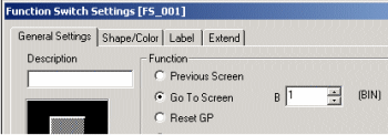
Please use [Change Screen] of Function Switch. |
| [Method 2] |
Using T Tag [Word] Setting or Word Switch. |
|
|
| [[Method 3] |
Changing the screens by PLC. |
|
Please wi rte the data on +8 of System Data Area by PLC. |
|
|
*Please check [Method 3] in case to use both [Method 1.2] and [Method 3]. |
*The System Data Area will be +15 in case of using Memory Link System. |
|
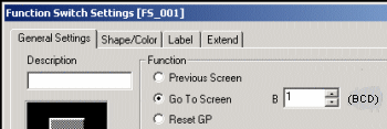
| [Method 1] Using Function Switch from Parts. |
| |
| |
 |
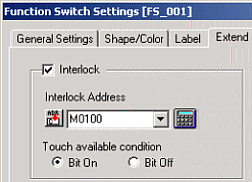
Have you set Interlock? |
|
| |
If you have set Interlock, please check Interlock off to unlock. |
| |
 |
| |
|
| |
|
 |
Please check the Data Type. |
|
| |
|
| |
| 1. |
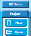
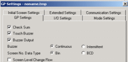
Please select [GP Setup] on [Project Manager] and open [GP Settings].
Please select [Bin] or [BCD] for [Screen No. Data Type] on [GP Settings]. |
| |
|
| |
|
| 2. |
Please display [Function Switch Setting], and check if [Screen Number] displays [Bin] or [BCD] which you have set in Process 1. |
| |
BIN
BCD
 |
| |
Depending on which you have selected [Bin] or [BCD] in Process 1, the Data System which will be displayed in Process 2 will be different. |
|
| |
|
| |
|
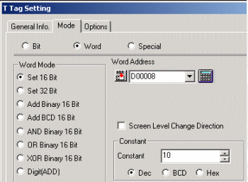
[Method 2] Using T Tag [Word] Setting or Word Switch from Parts. |
| |
| |
|
Have you stored the data in LS8 or +8th address of System Start Address (*1) ? |
|
| |
*The System Data Area will be +15 in case of using Memory Link System. |
| |
|
| |
There are 2 types of address to change the screens |
| |
| [Method 1] |
Using [LS Area], Word Address of GP. |
|
The screen will be changed if you store the Screen Number on [LS8] from [LS Area], Word Address inside of GP. |
| [Method 2]
|
Using System Data Area which is assigned to PLC |
|
It is possible to assign 20 words of System Data Area to PLC Data Register when [GP Settings] or Offline Mode of GP.
The screen will be changed if you store the Screen Number on +8th address in there.
|
|
|
| |
|
| |
(Ex.) How to assign System Area by GP-PRO/PB3 C-Package |
| |
|
|
|
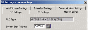
| (Ex.) In case that D0 is assigned to System Start Address, the Range of Screen Change will be D8. |
|
| |
|
|
Is the Data Type proper? |
|
| |
|
| |
Please select [Set 16 Bit] from [Word Mode] in case you are using T Tag ( it will not operate with [Set 32 Bit]). Please select [Dec] (Decimal Numbers), [BCD](Binary Decimal Numbers), or [HEX] (Hexadecimal Numbers) from [Constant].
In case that Word Switches from Parts are used, [Dec] will be selected automatically. It is not possible to designate the Data Type. |
| |
 |
| |
|
| |
Please check if the Data Type which you have set on T Tag matches with [Screen No. Data Type] on [GP Settings]. In case that you have selected [Dec] (decimal number) on T Tag, please select [Bin] if Word Switches are used. |
| |
|
| |
| It is also possible to check it on GP. |
Please display Offline Mode on GP, and follow as [1: Initial Settings] - [1: System Environment Setup] - [System Settings].
|
|
|
| |
|
| [Method 3] Changing the screens by PLC. |
| |
| |
|
Are you using both Screen Change by Switch and Screen Change by PLC at the same time? |
|
| |
|
| |
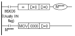
If you are using Screen Change by Switch and Screen Change by PLC at the same time, there is a possibility, with some conditions, that you can not change the screens. Therefore, please compare the +0 data and the +8 data in System Data Area, and if the datum are equal, please add the program such as which clears +8 to 0. |
| |
|
| |
(Ex.)PLC Ladder Program of Mitsubishi Elec. |
| |
|
| |
| Reason why the screens are not changed |
| In case of Screen Change by Switch, any data of Screen Change Number will not be written on +8 in System Data Area at all and GP will change screens automatically. Therefore, the data before Screen Change will remain at the address of +8.
Click here for details of Screen Change |
|
|
| |
|
| |
| In case of Memory Link type |
| Same symptom will occur in case of Memory Link Type. In this case, please write the command which zeroes Address 15 before transferring the command which writes Screen Number at Address 15, and please transfer the Screen Number after this. |
|
|
| |
|
|
Is System Start Address correct? |
|
| |
|
| |
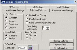
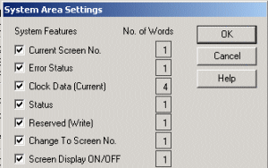
Please click [GP Setup] on Project Manager, and select [Expanded Settings] and then click [System Area]. |
| |
|
| |
|
| |
② [System Area Setting s] window will display. Please confirm the check box of [Change To Screen No.] is ON. |
| |
 |
| |
|
| |
| It is also possible to check it on GP. |
lease display Offline Mode on GP, and follow as [1: Initial Settings] - [1: System Environment Setup] - [System Area Setup]. Please refer this for details.
|
|
|
| |
|
| |
Other Checking Points |
|
There is the function called Rebuild which optimizes the screen and repairs the data. When you find something wrong with operation, please try Rebuild or Force System Setup.
Please see How to run Rebuild
A How to transfer with Force System Setup on
* When you transfer with Force System Setup on, memory will be initialized.
That causes the settings deleted when you transfer it with Force System Setup on if you have changed the settings such as System Settings on Offline Mode of GP.
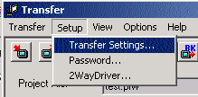
Therefore, please receive Project File from GP and backup once, besides, please confirm [GP System Screen] of [Transfer Settings] is checked ON before you transfer. |
Screen Level Change |
It is possible to create Level Structure between Screens in case that [Screen Level Change Flow] on such as T Tag, Word Switch, GP Setup is checked on. However, if this function is checked on unnecessarily, the screens will not change properly, also [Return to Previous Screen] Switch will not be available.
Please click here for details. |
GP-H70 Screen Change |
When the Operation Switch is available, please touch the Screen with touching the Operation Switch at the same time, to make Touch Input available. |
Simulation Mode
(GP70/77 Series only) |
Please check whether Simulation Mode is displayed or not.
If you can see SIM-LINK at the bottom left of the screen on Offline Mode, Simulation Mode is running. When you transfer, please check off [Send Simulation Data] of [Transfer Settings] . |
|
|
| |
| |