![]()
-
Part of the settings can also be set up with logic program I/O driver instructions.
 32.23 I/O Driver Instructions
A 2-phase counter is a counter that takes two input terminals to measure the input signal of a 2-phase input.
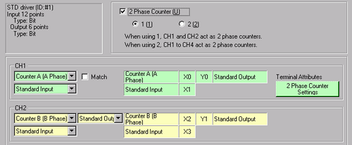
You can use maximum of two 2-phase counters in the LT3000 Series or STC6000 Series. When you use one, you use X0 and X2 input terminals, and when you use two, you use X0 and X2 as well as X4 and X6 input terminals. In the LT4000 Series, you can use one 2-phase counter with X0 and X1 input terminals.
Because multiple input terminals are occupied, arrangement of mapped terminals will differ from that of a single counter. Feature and setting methods for preload input, prestrobe input, and matching input are the same as that of a single counter.
The main functions of the 2-phase counters are indicated in the following table.
![]()
Part of the settings can also be set up with logic program I/O driver instructions.
![]() 32.23 I/O Driver Instructions
32.23 I/O Driver Instructions
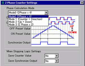
As for measuring methods, there are four types of modes ranging from "Phase Counting Mode 0" to "Phase Counting Mode 3".
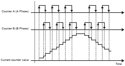
Mode 0 (2 Phase x 4)
When Counter A (Phase A) is ahead of Counter B (Phase B), operates as an up counter. When Counter A (Phase A) is lagging behind Counter B (Phase B), operates as a down counter.
In the LT4000 Series, you can reverse up-count and down-count by selecting [2 Phase x 4 Reverse].
Counter A (Phase A) is ahead of Counter B (Phase B)
|
Counter A (Phase A) |
Counter B (Phase B) |
Operations |
|
1 (High) |
Positive transition |
Up Count |
|
0 (Low) |
Negative transition |
|
|
Negative transition |
1 (High) |
|
|
Positive transition |
0 (Low) |
Counter A (Phase A) is lagging behind Counter B (Phase B)
|
Counter A (Phase A) |
Counter B (Phase B) |
Operations |
|
0 (Low) |
Positive transition |
Down Count |
|
1 (High) |
Negative transition |
|
|
Negative transition |
0 (Low) |
|
|
Positive transition |
1 (High) |
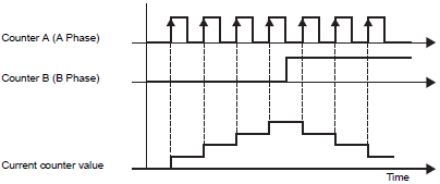
Mode 1 (Counter + Direction)
Begins counting at the positive transition of Counter A (Phase A). If Counter B (Phase B) is 0 (Low), counts up. If 1 (High), counts down.
This feature is supported by the LT3000 Series and STC6000 Series only.
Counter A (Phase A) is ahead of Counter B (Phase B)
|
Counter A (Phase A) |
Counter B (Phase B) |
Operations |
|
1 (High) |
Positive transition |
Not count |
|
0 (Low) |
Negative transition |
|
|
Negative transition |
1 (High) |
|
|
Positive transition |
0 (Low) |
Up Count |
Counter A (Phase A) is lagging behind Counter B (Phase B)
|
Counter A (Phase A) |
Counter B (Phase B) |
Operations |
|
0 (Low) |
Positive transition |
Not count |
|
1 (High) |
Negative transition |
|
|
Negative transition |
0 (Low) |
|
|
Positive transition |
1 (High) |
Down Count |
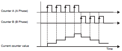
Mode 2 (Up + Down)
On Counter A's (Phase A) positive transition, if Counter B (Phase B) is 0 (Low), operates as an up counter. On Counter B's (Phase B) positive transition, if Counter A (Phase A) is 0 (Low), operates as a down counter.
This feature is supported by the LT3000 Series and STC6000 Series only.
Counter A (Phase A) is ahead of Counter B (Phase B)
|
Counter A (Phase A) |
Counter B (Phase B) |
Operations |
|
1 (High) |
Positive transition |
Not count |
|
0 (Low) |
Negative transition |
|
|
Negative transition |
1 (High) |
|
|
Positive transition |
0 (Low) |
Up Count |
Counter A (Phase A) is lagging behind Counter B (Phase B)
|
Counter A (Phase A) |
Counter B (Phase B) |
Operations |
|
0 (Low) |
Positive transition |
Down Count |
|
1 (High) |
Negative transition |
Not count |
|
Negative transition |
0 (Low) |
|
|
Positive transition |
1 (High) |
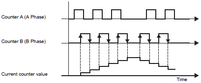
Mode 3 (2 Phase x 2)
Begins counting at a Counter B (Phase B) positive or negative transition. When Counter A (Phase A) is ahead of Counter B (Phase B), counts up. When Counter A (Phase A) is lagging behind Counter B (Phase B), counts down.
In the LT4000 Series, you can reverse up-count and down-count by selecting [2 Phase x 2 Reverse].
Counter A (Phase A) is ahead of Counter B (Phase B)
|
Counter A (Phase A) |
Counter B (Phase B) |
Operations |
|
1 (High) |
Positive transition |
Up Count |
|
0 (Low) |
Negative transition |
|
|
Negative transition |
1 (High) |
Not count |
|
Positive transition |
0 (Low) |
Counter A (Phase A) is lagging behind Counter B (Phase B)
|
Counter A (Phase A) |
Counter B (Phase B) |
Operations |
|
0 (Low) |
Positive transition |
Down Count |
|
1 (High) |
Negative transition |
|
|
Negative transition |
0 (Low) |
Not count |
|
Positive transition |
1 (High) |
Phase Calculation Mode Settings
LT3000 Series / STC6000 Series
From the [Project] menu, point to [System Settings] and click [I/O Driver].
On the [Internal Driver 1] screen, select the [2 Phase Counter] check box and click [2 Phase Counter Settings].
The [2 Phase Counter Settings] dialog box appears. Select the phase calculation mode from the pull-down menu.
LT4000 Series
From the [Project] menu's [System Settings], click [I/O Driver] and select the [2 Phase Counter].
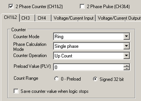
Select a mode from [Phase Calculation Mode] in the [CH1&2] tab.