The Counter Input Filter is a function that filters the switching of input signals that are counted by the high speed counter. Select a filter time to count input signals that switch between ON and OFF at intervals of that time or longer.
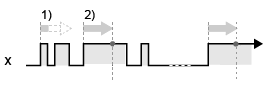
The following example illustrates input signal detection and filter time operation.
Counter Operation: Up Count
Edge Settings: Positive Transition
![]() : Filter Time
: Filter Time
x: Input Signal
1) Start counting the filter time from the rising edge of input signal "x". If the input signal turns OFF before the filter time has elapsed, the input signal is not detected and is not counted.
2) If the input signal is still ON after the filter time has elapsed since the rising edge of input signal "x”, the input signal is detected and counted.
Select the filter time for the input signal from the following.
None
Input signals are not filtered.
4 µs
If the input signal switches between ON and OFF at intervals of less than 4 µs, the high speed counter will not increment.
If the input signal switches at the intervals of between 4 µs and less than 5 µs, the high speed counter may or may not increment.
If the input signal switches at the intervals of 5 µs or greater, the high speed counter will increment.
40 µs
If the input signal switches between ON and OFF at intervals of less than 40 µs, the high speed counter will not increment.
If the input signal switches at the intervals of between 40 µs and less than 50 µs, the high speed counter may or may not increment.
If the input signal switches at the intervals of 50 µs or greater, the high speed counter will increment.
Configuring Counter Input Filter
LT4000 series
From the [Project] menu, point to [System Settings] and click [I/O Driver]. Select [High Speed Counter] in [Function].
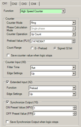
Configure [Counter Input] - [Filter Time].
STC6000 Series
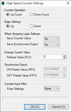
From the [Project] menu, point to [System Settings] and click [I/O Driver]. On the [Int.Driver 1] tab, click [High Speed Counter Settings].
Configure [Counter Input Filter] - [Filter Settings].