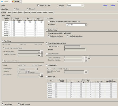
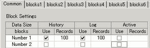
You can set the block, display mode, and the number of Alarm Histories stored for Alarm Message (History).
![]()
When using display units that support the SD card, "CF"/"CF Card" is replaced with "SD"/"SD Card".
Set the display mode and the number of Alarm History records (the number of Alarm Histories stored in the display unit) in each mode for each block.
Block
A group of Alarm Messages to be registered. A maximum of 8 blocks can be used.
Display mode
Choose the Alarm Message display method from [History], [Log], or [Active]. Choose [Active] to display only alarms which are currently triggered. To display old alarms as well, choose [History] or [Log].
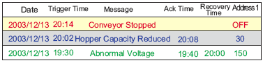
History
Displays Alarm Messages, data, trigger date, and time, in the order they are triggered. The time when the Alarm is acknowledged or recovered will be added to the same row. The change in the state of each Alarm can be viewed on a single row.
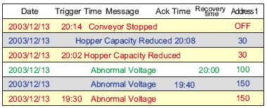
Log
The messages, date/time, and read data are displayed in separate rows every time the state changes from [Trigger], [Acknowledged], to [Recovery]. The date can be viewed in every state.
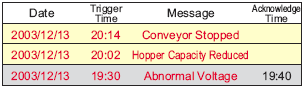
Active
Only [Trigger] alarms are displayed. When an alarm recovers, it is automatically erased.
Usage
Select the [Display Mode] to be used. A total of 8 display modes at maximum can be set for the whole Alarm History.
Records
Set the number of Alarm Histories stored for each display mode. When triggered alarms exceed the specified number, the oldest alarm is deleted.
This number varies depending on the display unit model and the [Alarm Type] setting.
|
Display Unit |
Number of records for [Basic] |
Number of records for [Extended] |
|
IPC Series |
10000 |
10000 |
|
SP5000 Series*1 GP4000 Series GP6000 Series GPH6000 Series |
768 |
2048 |
|
Other Models |
768 |
768 |
*1 When using the SP5000 Series Open Box, you can record the same number of records as the IPC Series by selecting [Folder] in [System Settings] - [Display Unit] - [WinGP] - [Historical Data Retentive Settings] - [Save in].
Select whether or not to print the Alarm History.
![]() 20.13.2 Restrictions for Printing Alarm History
20.13.2 Restrictions for Printing Alarm History
Real-time Print/Batch Print
Choose the printing timing from [Real-time Print] or [Batch Print].
Alarm history is printed every time an alarm is [Triggered], [Acknowledged], and [Recovery].
The print format is the same as the display format of [Log].
Even when two or more blocks are used, printing is performed as occasion arises regardless of the block.
When the bit 0 in [Print Word Address] is turned ON, the whole Alarm Histories stored in the designated block are printed.
The print format is determined by the [Display Mode] settings.
The settings are checked in the order of [History], [Log], [Active], and data is printed in the format of the first [Display Mode] set [On].
For example, when printing block 1
In this case, the block is printed using [History] format. If [History] were not set, the data would be printed using [Log] format. A page feed occurs after printing.
Multiple Line Message Printing
Specify whether to print alarm messages on lines separate from other information when printing. Since the message display area expands, you can quickly verify contents of long messages. You can print a maximum of 6 lines (one line for date/time + 5 lines of message) for one alarm. The number of lines depends on the message being registered.
![]()
If a message is more than five lines and uses text table, the message from the sixth line onward will not be printed.
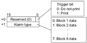
Print Word Address
This address controls the printing of the Alarm History. After setting the type of alarm, turn ON the trigger bit (bit 0) to start printing.
Completion Bit Address
Set the bit address that will tell you when printing has completed. This bit will turn ON when printing finishes.
![]()
After the [Completion Bit] has been confirmed as ON, please turn it OFF again. It is recommended to turn OFF the bit 0 of [Print Word Address] also at this time.
Displays the [Print Format Settings] dialog box.
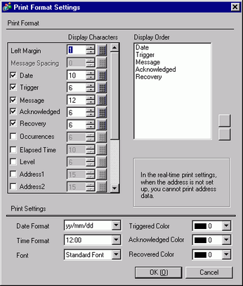
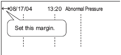
Left Margin
Select the spacing between the character of the left-most item and the border from 0 to 100 characters.
Message Spacing
You can define this when [Alarm Parts]-[Basic]-[Message Display Method]-[Multiple line display] is selected. The maximum number of characters that can display on one line is 160 characters. The number of characters in the message that can display on one line is 160 characters minus the total of [Display Characters] and [Left Margin]. Set [Display Characters] from 0 to 20.
Select blocks to print
From [Date], [Trigger], [Message], [Acknowledged], [Recovery], [Occurrences], [Elapsed Time], [Level], and [Address 1] to [Address 8], specify items to print.
Date
Prints the date when the alarm was triggered.
Trigger
Prints the time when the alarm was triggered.
Message
Prints Alarm Message.
![]()
When [Alarm Parts]-[Basic]-[Message Display Method]-[Multiple line display] is selected, messages are always displayed and you cannot clear the check box.
Acknowledge
Prints the time when the alarm message was confirmed.
Recovery
Prints alarm's recovery time.
Occurrences
Prints the number of times the alarm was triggered. The maximum count is 65535.
Elapsed Time
Prints the total duration of time when the alarm was in the triggered state. The maximum duration is 9999 hours 59 minutes 59 seconds.
Level
Prints the alarm's importance level.
Address1 - Address8
Prints data that is retrieved when the alarm is triggered, acknowledged, or recovered.
Display Characters
Set the number of characters displayed for each item. Each item's setting range is as follows.
|
Date |
5 to 100 or 8 to 100 single-byte characters (The setting range differs depending on the selected date format) |
|
Trigger, Acknowledged, Recovery |
5 to 100 or 8 to 100 single-byte characters (The setting range differs depending on the selected time format) |
|
Message |
1 to 160 single-byte characters (up to 192 characters when [Alarm Type] is set to [Extended]) |
|
Occurrences, Elapsed Time, Level |
2 to 100 single-byte characters |
|
Addresses 1 to 8 |
0 to 100 single-byte characters |
![]()
When you want to provide spaces between the items, set [Total Display Digits] larger than the number of characters that will actually be displayed.
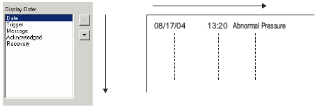
Display Order
Set the display order of all items. Blocks starting from the top of this list will be printed from left to right.
Date Format
Choose a print format for the date from [yy/mm/dd], [mm/dd/yy], [dd/mm/yy], and [mm/dd].
Time Format
Choose a print format for the time from [12:00], [24:00], [12:00:00] or [24:00:00].
Font
Choose a font type for the Alarm Message from [Standard Font] or [Stroke Font].
Triggered Color/Acknowledged Color/Recovered Color
Choose from 8 colors for the Alarm Message's [Trigger], [Acknowledged], and [Recovery] colors. Messages are printed in the specified colors regardless of the display unit type.
![]()
When white is selected, messages are printed in black.
When the [Display Mode] is [History] and [Batch Print] is set, the trigger color will be used when printing a triggered alarm, the acknowledge color for an acknowledged alarm, and the recovery color for a recovered alarm. However, when acknowledging a previously recovered alarm, the recovery color will be used for printing. The color setting is effective for text only. The background color will not be printed.
CSV Settings
Set the format to save in CSV format.
Multiple Line Message Output (Save Alarm to CSV)
Specify whether to print alarm messages on lines separate from other information. Since the message display area expands, you can quickly verify contents of long messages. A maximum of five lines for one alarm message can be printed. The number of lines depends on the message being registered.
![]()
If a message is more than five lines and uses text table, the message from the sixth line onward will not be printed.
Date Format
Select the [CSV Date Format] from [yy/mm/dd], [dd/mm/yy], [mm/dd/yy], [20yy/mm/dd], [dd/mm/20yy], [mm/dd/20yy], or [mm/dd]. "yy" displays the last two digits of the year, and "mm" and "dd" use two digits to display the month and date.
![]()
To read log data from the CF card using Pro-Server EX (GP log data upload and reading of Excel report log data), choose [yy/mm/dd]. If you select an option other than [yy/mm/dd], the date may be read out incorrectly.
When using the MES action's Get CF Alarm History File in Pro-Server EX before V1.32, select [yy/mm/dd]. If you select an option other than [yy/mm/dd], either an error will occur or the incorrect date is saved in the database.
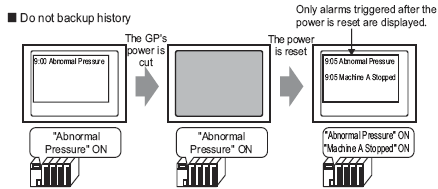
Define whether or not to save Alarm History to the display unit's backup memory (SRAM).
![]() 2.3 About the Display Unit's Internal Data
2.3 About the Display Unit's Internal Data
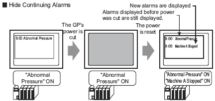
When backup is not selected and the display unit is turned OFF, all the Alarm Histories displayed before are erased. When the display unit is turned ON again, only the alarms triggered at the time and afterward are displayed.
![]()
GP-4100 series (excluding GP-411*T3) display units back up the alarm history to virtual memory instead of SRAM.
![]() 2.3 About the Display Unit's Internal Data
2.3 About the Display Unit's Internal Data
When the [Alarm Type] is [Extended], the accumulated time and number of occurrences are not saved in the backup SRAM. If you do not want to delete data after turning off the display unit, set the [Retentive Accumulation/Count] option.
Alarm Continuous Action at Power ON
If the value of device/PLC in the [Trigger Condition] remains the same before and after the device/PLC is turned off/on, the system uses this setting for displaying the alarm.
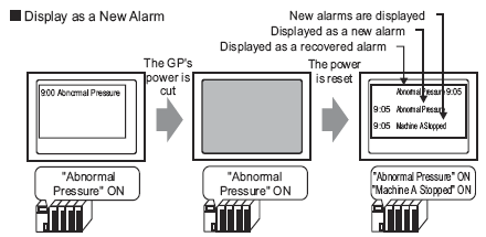
Display as a new Alarm
When you restart the display unit, the status of all previous alarms change to "recovered", except for the active alarms. The active alarms are shown as newly triggered alarms.
However, if you have specified any of the following settings, the previous alarms remain on the screen after the restart. This is true, even if the value of device/PLC specified in the [Trigger Condition] stays zero or if you have selected [Display as New Alarms].
In [Bit Monitoring], [Trigger Condition] is OFF.
In [Word Monitoring], the Alarm Value of [Trigger Condition] is zero.
In [Word Monitoring], the Alarm Range of [Trigger Condition] contains zero.
Hide Continuing Alarms
All previous alarms remains on the screen after the Display Unit is restarted.
Behaviors of Back-up Function (when [Trigger Condition] is ON)
Storage Frequency
When using GP-4100 series (excluding GP-411*T3), set up the frequency for saving alarm history data to virtual backup memory from 1 to 60 minutes.
When the defined frequency elapses, if there are no data changes from the previous save, the storage operation does not take place.
You can store history data up to 200,000 times.
|
|
|
LOSS OF DATA
Failure to follow these instructions can result in equipment damage. |
Append Date/Time to file name
Specifies whether to append to the file name the time stamp (year, month, date, and time when the save to CSV operation starts).
When check box is cleared
The file name will consist of "Z" to indicate alarm messages + the file number (5 digits). The file number value is stored in the address following the [Control Word Address].
For example, when file number is 1, file name is "Z00001.csv"
When check box is selected
The file name will consist of "Z" to indicate alarm messages + the file number (5 digits) + time stamp. The time stamp format is defined in the [Date/Time Format] field.
For example, When file number is 1, the save date and time is 2017/3/16 12:05:30, the Date/Time Format is _%Y%M%D_%h, the file name is "Z00001_20170316_12.csv".
![]()
For models that support appending the date and time to CSV file names, refer to the following.
![]() 1.5 Supported Features
1.5 Supported Features
Date/Time Format
When the [Append Date/Time to file name] check box is selected, set up the time stamp format with 16 single-byte characters or less. You can use single-byte alphanumeric characters, the following single-byte symbols, and the following macro symbols.
Single-byte symbols
% _ - ( )
Macro
|
Macro |
Description |
|---|---|
|
%Y |
Year (4 digit format) |
|
%y |
Year (2 digit format) |
|
%M |
Month |
|
%D |
Day |
|
%h |
Hours (24 hour time format) |
|
%H |
Hours (12 hour time format) |
|
%m |
Minutes |
|
%s |
Seconds |
|
% + any character except those above |
Adds any character string. "%" symbols at the beginning are not included in the file name. Example 1, when _%Y%M%D_%A is defined: Z00001_20170316_A Example 2, when _%Y%M%D_%% is defined: Z00001_20170316_% |
Preview
Based on the defined [Date/Time Format], displays an image illustrating the file name with the current date and time. When the format is invalid, the preview is not updated.
External Operation
Select whether or not to perform [Ack All], [Clear All], [Clear All Number of Occurrences], and [Clear All Accumulated Time] from the host (PLC).
![]() 20.14 How to Run External Operations from Multiple Display Units
20.14 How to Run External Operations from Multiple Display Units
Control Word Address
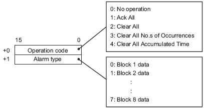
Set the address which will control the type of operation performed from the PLC (operation code), and the type of alarm.
When an external operation is performed, it handles all Alarm Messages in the block (active, history, log). For example, if you perform a [Clear All] on block 1, all Alarm Messages in block 1 (active, history, log) are cleared. Within a block, Active, History, and Log cannot be operated individually.
The operation's order is [History], [Log], [Active].
![]()
After the operation, please set the operation code to [0]. Otherwise, you cannot start a new operation.
Design the system such that the [Control Address] and [Completion Bit Address] are set to zero at the startup. This is a precaution for when the display unit is turned OFF during operation.
Completion Bit Address
Set the address which will monitor the completion of the operation. This bit will turn ON when the operation finishes.
![]()
When you set the operation code to "0", the completion bit address turns OFF automatically.
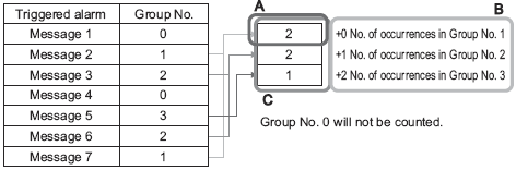
Select whether or not to use the Group feature. Set this feature to count the number of times that alarms have been triggered by group number.
Number of Alarms Start Address (Internal Device Word Address)
(A)
Set the start address in the display unit's internal device to write the number of alarm occurrences.
(B)
Among the addresses set up in (A), only those with the registered group number are used as the area for the writing frequency of internal device addresses.
(C)
Each time an alarm occurs, data in the corresponding group number's address (internal device) will be increased by 1.
![]()
The alarm occurrence counts from 0 to 65535.
The largest group number available is 6096. Hence, you can specify a different group number for every alarm message.
Please ensure that the number of groups is within the internal device's area (USR area or LS area). For the LS area, refer to the following.
![]() A.1.1 LS Area (Direct Access Method Area)
A.1.1 LS Area (Direct Access Method Area)
The alarm frequency gets erased when the display unit is turned OFF. When backing up the data, please use the internal device's backup feature.
![]() 5.4.4.3 Display Unit [Mode] - Backup Internal Device
5.4.4.3 Display Unit [Mode] - Backup Internal Device
When data is written to an internal device which stores alarm frequency or the display unit's power turns OFF, data are cleared and not counted properly.
The data format of the alarm frequency is fixed as Bin.
Alarms with group number 0 are not counted.
Save Accumulation/Count
Specify whether the accumulated time of an alarm and the number of times an alarm is triggered is saved to an external storage device when [Alarm Type] is set to [Extended].
![]()
When [Retentive Accumulation/Count] is not set and the display unit is turned OFF, the accumulated time and the number of occurrences is set to "0".
Be sure to select the [Backup History] check box.
Save in
Select the "Save in" location from [CF card], [SD Card] and [USB storage].
Save Condition
Selects a condition to begin saving from [Frequency], [Bit ON], or [Bit Change].
Frequency
Set the save cycle (1 to 60 minutes).
Bit ON
Saves when the address specified in the Control Bit Address turns ON.
Bit Change
Saves when the address specified in the Control Bit Address changes (ON/OFF).
Frequency
When the [Save Condition] is set to [Frequency], set the save frequency (1 to 60 minutes).
Control Bit Address
When the [Save Condition] is set to [Bit ON] or [Bit Change], define the trigger bit address for saving.
Status Address
Specify the address where the save state will be stored.
|
Error Code |
Description |
Details |
|
0000h |
Output complete |
Output has completed successfully |
|
0001h |
Outputting |
Outputting |
|
2000h |
No data to write |
No data record |
|
3000h |
File write has failed |
The file is read-only or open. SD card is write protected |
|
4000h |
No external storage |
No external storage is inserted CF card cover is open |
|
5000h |
Read Error |
Reading from external storage failed. |
|
6000h |
Write Error |
The external storage does not have enough free space or the storage was disconnected during write operation. |
|
7000h |
External Storage Error |
External storage is not correctly formatted or is invalid. |
|
8000h |
Failed to read file |
The file format is not correct, or incompatible with the alarm settings in the display unit. |
![]()
If the file does not exist, the number of occurrences and the accumulated time become 0, and 8000h is stored as the status.
Send E-mail
Select the check box to send an e-mail to inform when an alarm is triggered/acknowledged/recovered. You can also inform when an Alarm History is saved in CSV.
Works when [Alarm Type] is set to [Basic] and the [Enable E-mail] check box is selected in the [System Settings] - [Email Settings]. Does not work when the [Alarm Type] is [Extended].
![]() 5.4.21 System Settings [E-mail] Settings Guide
5.4.21 System Settings [E-mail] Settings Guide
Refer to the Settings Menu for information about Mail settings.
Block
Select the Alarm blocks that will send e-mail.
Receiver Groups
Specify the receiver group number configured in [System Settings] - [E-mail].
E-mail Trigger
Select the e-mail trigger from [Trigger], [Acknowledged], [Recovery], or [Save CSV]. You can select multiple options.
When [Save CSV] is selected, an Alarm History CSV file is attached to the e-mail.
Launch RemoteHMI Link
For use with Pro-face Remote HMI. Select this check box to add a link to launch Pro-face Remote HMI and information such as display unit's IP address and the [Server name] configured in the [System Settings] - [Remote Viewer] - [Pro-face Remote HMI].
![]()
The link to launch Pro-face Remote HMI works only with the models with one or two LAN ports.
The link works only when the e-mail destination is an Android or iOS client. Additionally, Pro-face Remote HMI Ver.1.50 or later is required.
For information about the link operation, refer to the description about Deep Link in the Pro-face Remote HMI Q&A.
![]() https://www.pro-face.com/otasuke/qa/remotehmi/2002.html
https://www.pro-face.com/otasuke/qa/remotehmi/2002.html
Configure Alarm Messages to display as scroll banners.
![]() 20.12.1.4 Alarm Settings (Banner)
20.12.1.4 Alarm Settings (Banner)
This setting displays currently active alarms in a list.