Type B+ (GLC150-*41-XY32KF-24V) Specifications (End of sale)
Functional Specifications
| Model (Global Code) | GLC150-SC41-XY32KF-24V End of Sale: 2012/06/29 →Recommended Substitute | GLC150-BG41-XY32KF-24V (PFXGLC150BDBP) End of Sale: 2013/09/30 →Recommended Substitute | ||
|---|---|---|---|---|
| Type | STN Color LCD | Monochrome LCD | ||
| Display Colors | 64 Colors | Blue-mode | ||
| Backlight | CCFL (Service life: more than 36,000 at 24 hr. operation) |
CCFL (Service life: more than 25,000 at 24 hr. operation) |
||
| Resolution | 320 × 240 pixels | |||
| Nominal Display Area (mm) | 118.2(W) × 89.4mm(H) | 115.2(W) × 86.4mm(H) | ||
| Contrast Control | 8 levels of adjustment available via touch panel | |||
| Language Character Sets | ASCII: (Code page 850) Alphanumeric (incl. European characters) Chinese: (GB2312-80 codes) simplified Chinese fonts Japanese: ANK 158, Kanji: 6962 (JIS Standards 1 & 2) Korean: (KSC5601 - 1992 codes) Hangul fonts Taiwanese: (Big 5 codes) traditional Chinese fonts |
|||
| Text | 8 × 8 Dots | 40 char. × 30 rows | ||
| 8 × 16 Dots | 40 char. × 15 rows | |||
| 16 × 16 Dots | 20 char. × 15 rows | |||
| 32 × 32 Dots | 10 char. × 7 rows | |||
| Character Sizes*1 | 8 × 8, 8 × 16, 16 × 16, 32 × 32 dots | |||
| Font Sizes | Both height and width can be expanded 1, 2, 4, or 8 times | |||
| Memory | Application | FLASH EPROM 1MB | ||
| Data Backup | SRAM 96KB - uses lithium battery*2 | |||
| Control Memory | Variable Data Area |
SRAM 32KB - uses lithium battery*2 (Including bit, integer, timer, counter) |
||
| Program Area | FLASH EPROM 128KB | |||
| Clock Accuracy | ± 65 seconds/month (at room temperature) | |||
| Touch Panel | 16 × 12 keys/ screen - 1 or 2 point touch | |||
- The display font will differ depending on which (language) character, or which size you select.
- A Lithium battery's lifetime is:
10 years when the battery's ambient temperature is under 40â
4.1 years when the battery's ambient temperature is under 50â
1.5 years when the battery's ambient temperature is under 60â
When used for backup:
Approximately 60 days, with a fully charged battery
Approximately 6 days, with a half-charged battery
General Specifications
| Model (Global Code) | GLC150-SC41-XY32KF-24V GLC150-BG41-XY32KF-24V (PFXGLC150BDBP) | ||
|---|---|---|---|
| Electrical | Rated Voltage | DC24V | |
| Rated Voltage Range | DC20.4 to 28.8V | ||
| Allowable Voltage Drop | 10 ms or less | ||
| Power Consumption | 20W max. | ||
| Rush Current | 30A max. | ||
| Voltage Endurance | AC1000V, 10mA for up to 1 minute (between charging and FG terminals) |
||
| Insulation Resistance | 20MΩ or higher at DC500V (between charging and FG terminals) |
||
| Environmental | Ambient Operating Temperature*1 |
0 to 50â | |
| Storage Temperature | -20 to 60â | ||
| Ambient Humidity | 10 - 90% RH (non-condensing wetbulb temperature 39â or less) |
||
| Storage Humidity | 10 - 90% RH (non-condensing wetbulb temperature 39â or less) |
||
| Dust | 0.1mg/m3 or less (non-conductive levels) | ||
| Corrosive Gasses |
Free of corrosive gases | ||
| Atmospheric Endurance (Operation Altitude) |
800 to 1114hPa (2000 meters or lower) | ||
| Vibration Resistance | Compatible with IEC61131-2 When vibration is NOT continuous: 10Hz to 57Hz 0.075mm, 57Hz to 150Hz 9.8m/s2 When vibration is continuous: 10Hz to 57Hz 0.035mm, 57Hz to 150Hz 4.9m/s2 X, Y, Z directions for 10 times (80min.) |
||
| Noise Immunity | Noise Immunity:1500Vp-p Pulse Duration: 1µs, Rise Time: 1ns (via noise simulator) |
||
| Electrostatic Discharge Immunity |
Contact discharge of 6kV (IEC 61000-4-2 Level 3) | ||
| Structural | Grounding | 100Ω or less, or your country's applicable standard | |
| Rating | Equivalent to IP65f (JEM1030), NEMA#250 TYPE 4X/12*2 | ||
| External Dimensions (mm) |
207W × 157H × 75.8D | ||
| Weight | 1.5kg (3.3lb) or less | ||
| Cooling Method | Natural air circulation | ||
- Ensure that the temperatures both at the display surface and inside the panel are within the prescribed ambient temperature range during use. Use at temperatures outside this range may lead to malfunction.
- Limited to the front face after installation in a panel. Testing equivalent to IP65f conditions has been performed; however, performance cannot be guaranteed for every type of environment. If the product is subjected to an oil mist over an extended period of time, even when using the oil designated in the tests, or if the product is subjected to an extremely low-viscosity cutting oil, some oil penetration may result due to peeling of the front sheet. If this occurs, a countermeasure is required. The same kind of penetration, or plastic deformation, may also occur with oils other than those designated. Confirm ambient environment prior to installation. Furthermore, rubber gaskets that have been used for extended periods of time, and those that have been scratched or soiled after panel installation, may not provide sufficient protection. It is recommended that the rubber gasket be replaced periodically to ensure stable protection.
DIO Interface Specifications
Input
| Model (Global Code) | GLC150-SC41-XY32KF-24V GLC150-BG41-XY32KF-24V (PFXGLC150BDBP) |
|---|---|
| Input Voltage | DC24V |
| Max. Allowable Voltage | DC26.4V |
| Input Type | Sink/ Source input |
| Rated Current | 5mA (24V) |
| Input Resistance | 4.7kΩ |
| Standard Operating Range | ON voltage: 15V min., OFF voltage: 5V max. |
| Input Delay | OFF→ON 1.5 ms max., ON→OFF 1.5 ms max. |
| Common | 1 |
| Common Structure | 16 points/common |
| External Connection | 40-pin connector (also used for output) |
| Input Points | 16 |
| Input Signal Indication | LED lights for each point ON (logic side) |
| Isolation Method | Photocoupler isolation |
| External Power Supply | For Signal: DC24V |
Output
| Model (Global Code) | GLC150-SC41-XY32KF-24V GLC150-BG41-XY32KF-24V (PFXGLC150BDBP) |
|---|---|
| Input Voltage | DC24V |
| Allowable Voltage Range | DC24V ±10% |
| Output Type | Sink output |
| Max. Load Current | 0.2A/point, 1.6A/common |
| Output Voltage Drop | 1.5V or less |
| Output Delay | OFF→ON: 1ms max., ON→OFF: 1ms max. |
| Leakage Current when OFF | 0.1mA or less |
| Output Classification | Transistor output |
| Common | 1 |
| Common Structure | 16 points/common |
| External Connection | 40-pin connector (also used for input) |
| Output Protection Classification | No protection |
| Internal Fuse | 3.5A chip fuse (not replaceable) |
| Surge Suppression Circuit | Diode |
| Output Points | 16 |
| Output Signal Indication | LED lights for each point ON (logic side) |
| Isolation Method | Photocoupler isolation |
| External Power Supply | For Signal: DC24V |
DIO Interface Connector Specifications, Circuit Diagrams
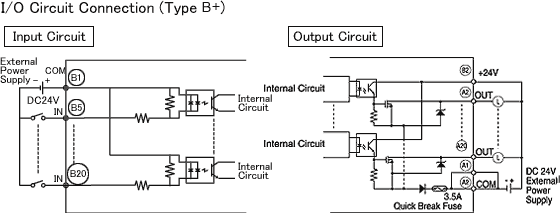
The sink/source type DIO integrates 16 input/ output (sink output only) points into a compact unit.
The Type B+ LT model supports up to 16-point inputs and 16-point outputs, ideal for connecting peripheral I/O devices.
DIO Connectors (Type B+: Sink Output)
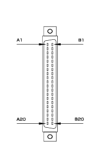
| Pin | Signal | Pin | Signal | Front View*1 |
|---|---|---|---|---|
| A1 | COM (0V: DOUT) | B1 | COM (24V: DIN) |  |
| A2 | COM (0V: DOUT) | B2 | DC24V (DOUT) | |
| A3 | NC | B3 | NC | |
| A4 | NC | B4 | NC | |
| A5 | DOUT15 | B5 | DIN15 | |
| A6 | DOUT14 | B6 | DIN14 | |
| A7 | DOUT13 | B7 | DIN13 | |
| A8 | DOUT12 | B8 | DIN12 | |
| A9 | DOUT11 | B9 | DIN11 | |
| A10 | DOUT10 | B10 | DIN10 | |
| A11 | DOUT9 | B11 | DIN9 | |
| A12 | DOUT8 | B12 | DIN8 | |
| A13 | DOUT7 | B13 | DIN7 | |
| A14 | DOUT6 | B14 | DIN6 | |
| A15 | DOUT5 | B15 | DIN5 | |
| A16 | DOUT4 | B16 | DIN4 | |
| A17 | DOUT3 | B17 | DIN3 | |
| A18 | DOUT2 | B18 | DIN2 | |
| A19 | DOUT1 | B19 | DIN1 | |
| A20 | DOUT0 | B20 | DIN0 |
- This front diagram shows the connector on the DIO unit side. When preparing the cable, note that the A and B stamps indicate the number 1 pins.

Recommended Connectors and Covers
Note: Connectors and Covers are not included with the unit.
| Manufacturer | Connection Method | Applicable Connector |
|---|---|---|
| Digital Electronics Corporation | Solder type | GLC100-DIOCN01 |
| Ribbon Cable Crimp Connector | GLC-DIOCN02 |
| Manufacturer | Connection MethodApplicable Connector | |
|---|---|---|
| Fujitsu Takamizawa Components |
Solder type | FCN-361J040-AU(Connector) |
| FCN-360C040-B(Cover) | ||
| Crimp type | FCN-363J040(Connector) | |
| FCN-363J040-AU/S(Contact) | ||
| FCN-360C040-B(Cover) | ||
| Press-fit type | FCN-367J040-AU/F (Connector) Flat Cable (1.27mm pitch) AWG#28 (Lay wire)/ AWG#30 (Solid wire) |
FCN-361J040-AU (Connector) and FCN-360C040-B (Cover)
* Digital offers 5/sets soldering type (connector/cover), manufactured by Fujitsu Takamizawa Components.
Remote I/O (FLEX NETWORK) Specifications
This I/F unit's high-speed remote I/O (6Mbps/ 12Mbps) is so fast, you won't think you are using a remote connection. Up to 1008 I/O points can be connected, with a communication delay of only 0.94ms (for 512 points at 12Mbps). The network can be extended up to 400 meters (2 channels at 6Mbps).
| Communication Configuration | 1: N |
|---|---|
| Connection Method | Multi-Drop Connection |
| Max. Distance | 200m/channel at 6Mbps,100m/channel at 12Mbps |
| Communication Method | Cyclic Time Division, half-duplex |
| Communication Speed | 6Mbps/ 12Mbps (selectable) |
| Communication I/F | Differential, pulse-transformer isolation |
| Error Check | Format, bit, CRC-12 verification |
| Max. Number of Nodes | 63 (number of occupied points varies according to I/O units) |
I/F Connector
 |
Pin No. | Signal Name | |
|---|---|---|---|
| 6 | Channel 2 shield (SLD) | ||
| 5 | Channel 2 communication data (TR-) | ||
| 4 | Channel 2 communication data (TR+) | ||
| 3 | Channel 1 shield (SLD) | ||
| 2 | Channel 1 communication data (TR-) | ||
| 1 | Channel 1 communication data (TR+) | ||
Common I/F Specifications
Alarm Output
| Contact Ratio | AC125V at 0.15A (resistive load), DC24V at 0.6A (resistive load) |
|---|---|
| Set Time (at 20â) | 4ms or less |
| Reset Time (at 20â) | 4ms or less |
| Min. Switching Load | 1mA/DC5V |
| Initial Contact Resistance | 100mΩ or less |
Tool Connector
| Tool Connector | Asynchronous: TTL level non-procedural command Connect data transfer cable for transferring data from LT Editor. |
|
|---|---|---|
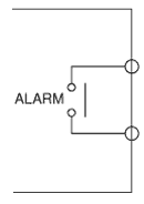
When LT Series is powered up and the system is booted, the relay of the alarm output circuit turns ON. When a major error or watchdog error occurs, this relay switch turns OFF. An external fail-safe circuit can be provided to monitor this relay output.
Note: This relay switch is OFF from the time the power is turned on until the LT Series system is booted. The external monitoring circuit must be started after the LT Seires system is booted.
| A timer circuit, which recognizes a non-operating LT is required. Otherwise the alarm monitoring system should be booted up after turning on the LT power supply. |
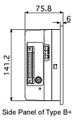
External Dimensions
Note: Panel thickness should be between 1.6 and 5.0 mm (0.06 to 0.02 in.), and should be based on the strength required to mount the LT to the panel.


