16DI/8DO
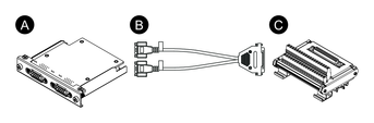
By using this digital I/O interface, you can control external I/O. Attach the interface unit to this product, and also use the cable included to connect to 16DI/8DO DIN rail terminal unit. The terminal unit is designed for mounting on the DIN rail.
-
When this 16DI/8DO interface is installed on the product, it does not comply with the UL certification.
-
The API and sample utility (including source code) are published on our website. For the file to download, refer to API.
Package Contents
-
16DI/8DO interface
-
Connection cable (2 m)
-
Terminal unit
Specifications
| Product number | PFXYP6MPX16Y8 | |
|
Connector |
D-Sub 15 pin (socket) x 2 |
|
|
Digital input |
Channels |
16 |
|
Input voltage |
Wet contact Logic 0: 0…3 Vdc, Logic 1: 10…30 Vdc Dry contact Logic 0: Open, Logic 1: GND |
|
|
Input current |
0.5 mA (10 Vdc) … 9 mA (30 Vdc) |
|
|
Over voltage protection |
70 Vdc |
|
|
Isolation voltage |
1,250 Vac |
|
|
Response time |
Typical: 50 μs (max.: 65 μs) |
|
|
Internal power supply for dry contact |
12 Vdc (max.: 2.3 mA/ch) |
|
|
Digital output |
Channels |
8 |
|
Output type |
MOS FET |
|
|
Output voltage |
5…30 Vdc |
|
|
Sink current (max.) |
100 mA/ch |
|
|
Isolation voltage |
1,250 Vac |
|
|
Response time |
Typical: 50 μs (max.: 65 μs) |
|
|
Counter |
Channels |
2 |
|
Resolution |
32 bit |
|
|
Input frequency (max.) |
When the de-bounce function is disabled: 10 kHz |
|
Pin Assignment
Module side: D-Sub 15 pin socket connector x 2
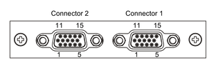
Connector 1
|
Pin No. |
Signal name |
Direction |
Description |
|---|---|---|---|
|
1 |
DI0/CNT0 |
Input |
Digital input ch0/Counter input ch0 |
|
2 |
DI1 |
Input |
Digital input ch1 |
|
3 |
DI2 |
Input |
Digital input ch2 |
|
4 |
DI3 |
Input |
Digital input ch3 |
|
5 |
DI4/CNT1 |
Input |
Digital input ch4/Counter input ch1 |
|
6 |
DI5 |
Input |
Digital input ch5 |
|
7 |
DI6 |
Input |
Digital input ch6 |
|
8 |
DI7 |
Input |
Digital input ch7 |
|
9 |
ECOM0 |
- |
External common of DI (ch0...7) |
|
10 |
EGND |
- |
External ground |
|
11 |
DO0 |
Output |
Digital output ch0 |
|
12 |
DO1 |
Output |
Digital output ch1 |
|
13 |
DO2 |
Output |
Digital output ch2 |
|
14 |
DO3 |
Output |
Digital output ch3 |
|
15 |
PCOM |
- |
Freewheeling common diode for DO |
|
Shell |
FG |
- |
Frame ground |
Connector 2
|
Pin No. |
Signal name |
Direction |
Description |
|---|---|---|---|
|
1 |
DI8 |
Input |
Digital input ch8 |
|
2 |
DI9 |
Input |
Digital input ch9 |
|
3 |
DI10 |
Input |
Digital input ch10 |
|
4 |
DI11 |
Input |
Digital input ch11 |
|
5 |
DI12 |
Input |
Digital input ch12 |
|
6 |
DI13 |
Input |
Digital input ch13 |
|
7 |
DI14 |
Input |
Digital input ch14 |
|
8 |
DI15 |
Input |
Digital input ch15 |
|
9 |
ECOM1 |
- |
External common of DI (ch8...15) |
|
10 |
EGND |
- |
External ground |
|
11 |
DO4 |
Output |
Digital output ch4 |
|
12 |
DO5 |
Output |
Digital output ch5 |
|
13 |
DO6 |
Output |
Digital output ch6 |
|
14 |
DO7 |
Output |
Digital output ch7 |
|
15 |
PCOM |
- |
Freewheeling common diode for DO |
|
Shell |
FG |
- |
Frame ground |
Recommended jack screw is #4-40 (UNC).
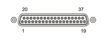
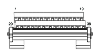
Pin Assignment of Terminal Unit
Terminal unit side: D-Sub 37 pin socket connector
|
Pin No. |
Signal name |
Direction |
Description |
|---|---|---|---|
|
1 |
DI0/CNT0 |
Input |
Digital input ch0/Counter input ch0 |
|
2 |
DI2 |
Input |
Digital input ch2 |
|
3 |
DI4/CNT1 |
Input |
Digital input ch4/Counter input ch1 |
|
4 |
DI6 |
Input |
Digital input ch6 |
|
5 |
DI8 |
Input |
Digital input ch8 |
|
6 |
DI10 |
Input |
Digital input ch10 |
|
7 |
DI12 |
Input |
Digital input ch12 |
|
8 |
DI14 |
Input |
Digital input ch14 |
|
9 |
ECOM0 |
- |
External common of DI (ch0...7) |
|
10 |
PCOM |
- |
Freewheeling common diode for DO |
|
11 |
DO0 |
Output |
Digital output ch0 |
|
12 |
DO2 |
Output |
Digital output ch2 |
|
13 |
DO4 |
Output |
Digital output ch4 |
|
14 |
DO6 |
Output |
Digital output ch6 |
|
15…19 |
NC |
- |
No connection |
|
20 |
DI1 |
Input |
Digital input ch1 |
|
21 |
DI3 |
Input |
Digital input ch3 |
|
22 |
DI5 |
Input |
Digital input ch5 |
|
23 |
DI7 |
Input |
Digital input ch7 |
|
24 |
DI9 |
Input |
Digital input ch9 |
|
25 |
DI11 |
Input |
Digital input ch11 |
|
26 |
DI13 |
Input |
Digital input ch13 |
|
27 |
DI15 |
Input |
Digital input ch15 |
|
28 |
ECOM1 |
- |
External common of DI (ch8...15) |
|
29 |
EGND |
- |
External ground |
|
30 |
DO1 |
Output |
Digital output ch1 |
|
31 |
DO3 |
Output |
Digital output ch3 |
|
32 |
DO5 |
Output |
Digital output ch5 |
|
33 |
DO7 |
Output |
Digital output ch7 |
|
34…37 |
NC |
- |
No connection |
|
Shell |
FG |
- |
Frame ground |
Recommended jack screw is #4-40 (UNC).
Screw terminal: 38 pin
|
Pin No. |
Signal name |
Direction |
Description |
|---|---|---|---|
|
1 |
DI0/CNT0 |
Input |
Digital input ch0/Counter input ch0 |
|
2 |
DI2 |
Input |
Digital input ch2 |
|
3 |
DI4/CNT1 |
Input |
Digital input ch4/Counter input ch1 |
|
4 |
DI6 |
Input |
Digital input ch6 |
|
5 |
DI8 |
Input |
Digital input ch8 |
|
6 |
DI10 |
Input |
Digital input ch10 |
|
7 |
DI12 |
Input |
Digital input ch12 |
|
8 |
DI14 |
Input |
Digital input ch14 |
|
9 |
ECOM0 |
- |
External common of DI (ch0...7) |
|
10 |
PCOM |
- |
Freewheeling common diode for DO |
|
11 |
DO0 |
Output |
Digital output ch0 |
|
12 |
DO2 |
Output |
Digital output ch2 |
|
13 |
DO4 |
Output |
Digital output ch4 |
|
14 |
DO6 |
Output |
Digital output ch6 |
|
15…19 |
NC |
- |
No connection |
|
20 |
DI1 |
Input |
Digital input ch1 |
|
21 |
DI3 |
Input |
Digital input ch3 |
|
22 |
DI5 |
Input |
Digital input ch5 |
|
23 |
DI7 |
Input |
Digital input ch7 |
|
24 |
DI9 |
Input |
Digital input ch9 |
|
25 |
DI11 |
Input |
Digital input ch11 |
|
26 |
DI13 |
Input |
Digital input ch13 |
|
27 |
DI15 |
Input |
Digital input ch15 |
|
28 |
ECOM1 |
- |
External common of DI (ch8...15) |
|
29 |
EGND |
- |
External ground |
|
30 |
DO1 |
Output |
Digital output ch1 |
|
31 |
DO3 |
Output |
Digital output ch3 |
|
32 |
DO5 |
Output |
Digital output ch5 |
|
33 |
DO7 |
Output |
Digital output ch7 |
|
34…37 |
NC |
- |
No connection |
|
38 |
FG |
- |
Frame ground |
Example Connection with External Device
Digital input circuit (wet contact)
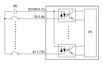
(A) Internal circuit
(B) 24 Vdc
Digital input circuit (dry contact)
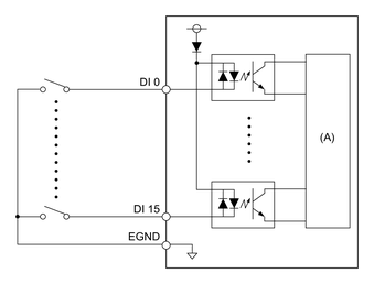
(A) Internal circuit
Digital output circuit
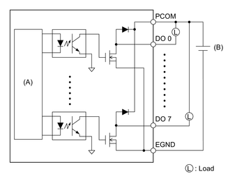
(A) Internal circuit
(B) 24 Vdc
Wiring of Terminal Unit
-
If the ends of the individual wires are not twisted correctly, the wires may create a short circuit.
-
Using a pin terminal with an insulating sleeve is recommended to prevent the possibility of a terminal short circuit.
-
Use copper wire rated for 75 °C (167 °F) or higher.
|
Recommended cross section |
0.5...2.5 mm2 (AWG 20...13) |
|
Conductor type |
Solid or stranded wire |
|
Conductor length |
6…7 mm (0.24…0.28 in)  |
|
Recommended pin terminals |
Cross section: 0.25...1.5 mm2 |
|
Recommended screwdriver |
Blade thickness: 0.6 mm (0.02 in) Blade width: 3.5 mm (0.14 in) |
Insert each cord wire into its corresponding hole and fasten the screws to clamp the wire in place.
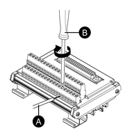
-
Cord
-
Screwdriver
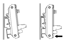
Installing to DIN Rail
Hook the upper groove of the unit onto the DIN rail, then push the bottom part onto the rail until you hear a click.
-
Use the DIN rail compatible with IEC 60715 TH35-7.5 for the terminal unit.
-
In environments where this terminal unit will experience extreme vibration and shock, affix this terminal unit to the DIN rail with compatible fasteners, as required.