A.2.1.2 Integer Type Logic System Variables - #L System Variables
|
Variable Name
|
Description
|
READ
|
WRITE
|
|
Scan Time
|
|
#L_ScanTime
|
The time from the start of step 0 of the current scan to the start of step 0 of the next scan
|

|
-
|
|
#L_AvgScanTime
|
The average of 64 #L_ScanTime cycles
|
|
-
|
|
#L_MinScanTime
|
The minimum scan time for #L_ScanTime
|
|
-
|
|
#L_MaxScanTime
|
The maximum scan time for #L_ScanTime
|
|
-
|
|
#L_ScanCount
|
Number of scans
|
|
-
|
|
#L_LogicTime
|
The time from the start of step 0 to the END instruction
|
|
-
|
|
#L_AvgLogicTime
|
The average of 64 #L_LogicTime cycles
|
|
-
|
|
#L_MinLogicTime
|
The minimum logic time for #L_LogicTime
|
|
-
|
|
#L_MaxLogicTime
|
The maximum logic time for #L_LogicTime
|
|
-
|
|
Status
|
|
#L_Status
|
Logic status information
|
|
-
|
|
#L_Platform
|
Code number of the display unit platform
|
|
-
|
|
#L_Version
|
Logic firmware version
|
|
-
|
|
#L_EditCount
|
Number of online edits
|
|
-
|
|
#L_ForceCount
|
Number of variables that are forcibly changed
|
|
-
|
|
#L_IOInfo
|
I/O driver information
|
|
-
|
|
#L_LogicInfo
|
Logic Information
|
|
-
|
|
#L_IOMasterDrv**1
|
Master I/O Driver Extended Information
|
Depends on the I/O Driver
|
Depends on the I/O Driver
|
|
#L_IOMasterDiag**4
|
Master I/O Driver Self Diagnosis Information
|
Depends on the I/O Driver
|
Depends on the I/O Driver
|
|
System Settings
|
|
#L_ConstantScan
|
Logic startup frequency
|
|
-
|
|
#L_PercentScan
|
Logic operation rate
|
|
-
|
|
#L_WatchdogTime
|
Logic WDT value
|
|
-
|
|
#L_AddressRefreshTime
|
Connection device address refresh time
|
|
-
|
|
Time
|
|
#L_Time
|
Time information
|
|
-
|
|
Operation Information
|
|
#L_Command
|
Changes the logic operation mode
|
|
|
|
#L_LogicMonitor
|
The logic monitor startup switch
|
|
|
|
#L_LogicMonStep
|
Indicates the steps for displaying the logic monitor
|
|
|
|
I/O Status
|
|
#L_IOStatus
|
Statu so I/O Driver
|
|
-
|
|
Error information
|
|
#L_CalcErrCode
|
Storage area for calculation error codes
|
|
-
|
|
#L_FaultStep
|
Storage area for the step Number of the calculation error
|
|
-
|
|
#L_FaultLogicScreen
|
Storage area for the logic screen number of the calculation error
|
|
-
|
|
Logic Stop
|
|
#L_StopScans
|
Number of logic stop scans
|
|
|
|
Retentive Variable Backup
|
|
#L_BackupCmd
|
Backup Command
|
|
|
|
Common to LT*2*3
|
|
#L_ExIOFirmVer*2
|
Extended I/O board firmware version
|
|
-
|
|
#L_ExIOSpCtrl*2
|
Special I/O control
|
|
|
|
#L_ExIOSpOut*2
|
Special output
|
|
-
|
|
#L_ExIOSpParmChg*2
|
Change Special I/O parameter
|
|
|
|
#L_ExIOSpParmErr*2
|
Special I/O parameter error
|
|
-
|
|
#L_ExIOAccelPlsTbl*2
|
Acceleration/deceleration pulse table
|
|
|
|
#L_ExIOCntInCtrl*2
|
Counter input control
|
|
|
|
#L_ExIOCntInExtCtrl*2
|
Counter input external control
|
|
|
|
#L_ExIOCntInState*2
|
Counter input state
|
|
|
|
#L_PWM*_WHZ*2*3
|
Ch* output frequency
|
|
|
|
#L_PWM*_DTY*2*3
|
CH* ON duty value
|
|
|
|
#L_PLS*_LHZ*2*3
|
Ch* output frequency
|
|
|
|
#L_PLS*_NUM*2*3
|
CH* Output Pulses
|
|
|
|
#L_PLS*_SHZ*2*3
|
Ch* Initial Output Frequency
|
|
|
|
#L_PLS*_ACC*2*3
|
CH* acceleration/deceleration time or acceleration time
|
|
|
|
#L_PLS*_DEC*2*3
|
CH* Pulse deceleration time
|
|
|
|
#L_PLS*_CHZ*2*3
|
CH* Current Frequency
|
|
-
|
|
#L_PLS*_CPC*2*3
|
CH* Current Pulse Output Value
|
|
-
|
|
#L_HSC*_MOD*2*3
|
Ch* count system
|
|
|
|
#L_HSC*_TB*2*3
|
CH* Time-Base when Sampling Mode is selected
|
|
|
|
#L_HSC*_PLV*2*3
|
Ch* preload value
|
|
|
|
#L_HSC*_PSV*2*3
|
Ch* pre-strobe value
|
|
-
|
|
#L_HSC*_ONP*2*3
|
CH* ON Preset Value
|
|
|
|
#L_HSC*_OFP*2*3
|
CH* OFF Preset Value
|
|
|
|
#L_HSC*_HCV*2*3
|
Current counter value of Ch*
|
|
-
|
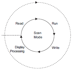
#L_ScanTime (The time from the start of step 0 of the current scan to the start of step 0 of the next scan)
Stores the scan time of the previous scan just before the execution of the next scan.
Scan time is the time required for I/O reading, execution of the logic program, I/O writing, and display processing.
The unit is 0.1 milliseconds.
#L_AvgScanTime (Average of 64 #L_ScanTime cycles)
Stores the average scan time.
Average scan time is the average time required for I/O reading, execution of the logic program, I/O writing, and display processing in one scan.
The variable is updated with each completion of 64 scan cycles.
The unit is 0.1 milliseconds.
#L_MinScanTime (Minimum scan time of #L_ScanTime)
Stores the minimum scan time of the logic program.
When #L_ScanTime is updated, the minimum scan check is performed and the variable is updated with every scan.
The unit is 0.1 milliseconds.
#L_MaxScanTime (Maximum scan time of #L_ScanTime)
Stores the maximum scan time of the logic program.
When #L_ScanTime is updated, the maximum scan check is performed and the variable is updated with every scan.
The unit is 0.1 milliseconds.
#L_ScanCount (Number of scans)
Upon completion of each logic program scan, the counter increments the variable.
The value in #L_ScanCount ranges from 0 to 16#FFFFFFFF. When the maximum value (16#FFFFFFFF) is exceeded, the variable is incremented again from 0.
You can confirm whether the logic program is being executed by checking #L_ScanCount.
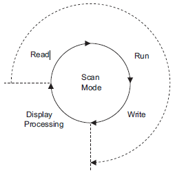
#L_LogicTime (Time from the start of step 0 to the END instruction)
Stores the logic time of the previous scan execution.
Logic time is the time required for I/O reading, execution of the logic program, and I/O writing in one scan. The display processing time is not included. The unit is 0.1 milliseconds.
#L_AvgLogicTime (Average of 64 #L_LogicTime cycles)
Stores the average logic time.
Average logic time is the average time required for I/O reading, execution of the logic program, and I/O writing in one scan.
The variable is updated with each completion of 64 scan cycles. The unit is 0.1 milliseconds.
#L_MinLogicTime (Minimum logic time of #L_LogicTime)
Stores the minimum logic time of the logic program.
When updating #L_LogicTime, the minimum logic time is checked and the variable is updated with every scan.
The unit is 0.1 milliseconds.
#L_MaxLogicTime (Maximum logic time of #L_LogicTime)
Stores the maximum logic time of the logic program.
When updating #L_LogicTime, the maximum logic time is checked and the variable is updated with every scan.
The unit is 0.1 milliseconds.
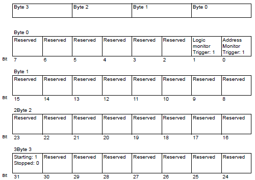
#L_Status (Logic status information)
Displays the state of the display unit. Bytes and bits are defined as follows:
Byte 0: Displays the current error state on the display unit.
Byte 1: Displays the error state history. This byte resets to 0 only when the display unit is reset.
Byte 2: Displays the current operation state.
Byte 3: Reserved area.

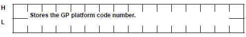
#L_Platform (display unit platform code number)
Stores the display unit platform code number.
0x00020404
0x00020504
0x00020514
0x00020B14
0x00020B34
0x00020614
0x00020714
0x00020814
0x00020634
0x00020734
0x00020834
0x00020934
0x00020A14
0x00020A34
0x00030204
0x00030504
0x00030514
-
SP5000 Series, GP4000 Series, GP6000 Series, LT4000 Series, ET6000 Series, ST6000 Series, STM6000 Series, STC6000 Series, GPH6000 Series
0x00040000
#L_Version (Logic firmware version)
Stores the logic firmware version.
#L_EditCount (Number of online edits)
Stores the number of online edits. (This variable will not execute while writing in RUN mode.)
#L_ForceCount (Number of variables that are forcibly changed)
Stores the number of variables that have been forcibly changed during online monitoring.
#L_IOInfo (I/O driver information)
Stores information on the I/O driver.
#L_IOInfo[0]: Internal Driver 2
#L_IOInfo[1]: Internal Driver 1
#L_IOInfo[2]: External Driver 1
#L_IOInfo[3]: Reserved
#L_LogicInfo (Logic Information)
Reserved by the System.
#L_IOMasterDrv* (Master I/O Driver Extended Information)
[*] = 0 to 255.
Stores Master I/O Driver Extended Information. Depending on the master I/O driver type, you may not be able to use some of the items.
 31.9.4 Using I/O Driver Instructions - CANopen
31.10.3 Using I/O Driver Instructions - EtherNet/IP
#L_IOMasterDiag* (Master I/O Driver Self Diagnosis)
[*] = 0 to 31.
Stores Master I/O Driver self diagnosis information. Depending on the master I/O driver type, you may not be able to use some of the items.
#L_ConstantScan (Logic startup frequency)
Stores the total process time of the logic when the Fixed San Time is selected.
When logic time is constant, the display processing time can be extended by increasing the value of #L_ConstantScan. By decreasing the value, the display processing time can be reduced. This is because most of the processing time is used by logic functions.
Set this as the default setting. The unit is 0.1 milliseconds.
30.14.3.2 Logic Scan Time
#L_PercentScan (Logic operation rate)
Stores the usage percentage of the logic function compared to the total logic processing time in CPU Scan Percentage mode.
Set this as the default setting.
30.14.3.1 Logic Features
#L_WatchdogTime (WDT value of the logic)
Stores the WDT value (watch dog timer) with 0.1ms as a unit.
When #L_ScanTime exceeds this value, a major error occurs.
Set this as the default setting. The unit is 0.1 milliseconds.
#L_AddressRefreshTime (Device/PLC address refresh time)
Stores the address refresh time for the connection device addresses used in the logic program. The unit is 0.1 milliseconds.
30.14.3.3 Address Refresh
#L_Time (Time information)
Indicates the "time" set in the logic in 4-digit BCD.
The time is stored in the following state:
For example, 11:19 PM
|
|
Hours (ten's column)
|
Hours (one's column)
|
Minutes (ten's column)
|
Minutes (one's column)
|
|
Value
|
2
|
3
|
1
|
9
|
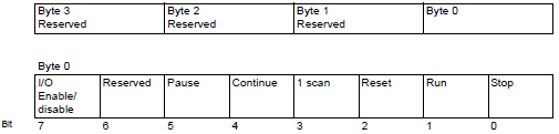
#L_Command (Changes the logic operation mode)
This is an integer variable used as a logic control command.
After the logic acknowledges #L_Command, bits other than bit 7 are reset to 0. If multiple bits are ON, the least significant bit takes priority.
#L_LogicMonitor (Startup switch of the logic monitor)
Starts up and operates the logic program monitor function on the display unit.
The following shows each operation.
#L_LogicMonStep (Instruction for displaying steps in the logic monitor)
Stores the number of the rung to display in the logic monitor.
If the logic monitor is not running, write the rung number in #L_LogicMonStep to start up the logic monitor with the specified rung number as the first rung when the logic monitor trigger bit (bit 0 of #L_LogicMonitor) turns OFF→ON.
This variable is used when the logic monitor function is enabled.
#L_IOStatus (Status of the I/O driver)
Stores I/O driver error information.
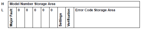
Model number of the unit where the error occurred is stored. This will be reserved bits depending on the I/O driver used.
When the I/O attribute of the specified unit is the same as that of the actually connected unit, but the points differ, "1" is set. This will be reserved bits depending on the I/O driver used.
When the I/O attribute of the specified unit is different from that of the actually connected unit, "1" is set. This will be reserved bits depending on the I/O driver used.
When a failure that stops the logic such as an auxiliary board ID conflict or project data failure is found, "1" is set.
When an I/O driver error occurs, an error message and the following error code will display on the display unit screen.
RGED***: Internal driver 2 error code
RGEE***: Internal driver 1 error code
RGEF***: External driver 1 error code
#L_IOStatus stores the number "***" (0 to 255) of these error codes in the bottom 8 bits.
The following explains the classification of each error code.
|
Error Code
|
Description
|
|
001-049
|
Project data error
|
|
050-099
|
Hardware error
|
|
100-199
|
Application error
|
|
200-254
|
Internal Errors
|
For more information about the error code of each I/O driver, please refer to the following:
T.7 Display-related errors
T.8 Errors displayed with an expansion unit
The array of each element is as follows.
#L_IOStatus[0]: Internal Driver 2
#L_IOStatus[1]: Internal Driver 1
#L_IOStatus[2]: External Driver 1
#L_IOStatus[3]: Reserved
#L_CalcErrCode
32 bit system variable that stores the error code generated by the logic program. You can confirm the last error that occurred by checking the value of this system variable. When an error code is saved, #L_Error turns ON.
Resetting the logic resets #L_CalcErrCode to 0. You can reset logic using #L_Command (change logic operation mode).
Error Code List
|
Error code (Dec)
|
Description
|
|
0000
|
-
|
No error.
|
|
0001
|
Minor error (continue/stop)
|
An overflow occurs when converting numbers, from real to integer, or 64-bit real to 32-bit real.
|
|
0002
|
Major error (stop)
|
A reference exceeded the array size.
|
|
0003
|
A reference exceeded the range of an integer.
|
|
0004
|
Stack overflow.
|
|
0005
|
An invalid instruction code is used.
|
|
0006
|
An error occurred during error handler processing.
|
|
0007
|
The scan time exceeded the WDT.
|
|
0008
|
Major error (stop)
|
The critical failure occurred on the I/O driver.
|
|
0009
|
Software error
|
|
0010
|
An invalid operand is used.
|
|
0011
|
-
|
Reserved
|
|
0012
|
Minor error (continue/stop)
|
BCD/BIN conversion error
|
|
0013
|
ENCO/DECO conversion error
|
|
0014
|
-
|
Reserved
|
|
0015
|
Minor error (continue/stop)
|
The SRAM data (user program) was destroyed
a destroyed FROM.
|
|
0016
|
The shift bit value exceeded the range.
|
|
0100
|
Major error (stop)
|
Major error occurred on I/O driver instruction
|
|
0105
|
Minor error (continue/stop)
|
Minor error occurred on I/O driver instruction
|
|
6706
|
Continue on error
|
The device Number and data value of the application instruction operand have exceeded the range.
|
|
6733
|
The proportion gain (Kp) is out of range (Kp<0).
|
|
6734
|
The integral calculus time (Ti) is out of range (Ti<0).
|
|
6736
|
The differential calculus time (Td) is out of range (Td<0).
|
|
6740
|
Sampling time (Ts) <= sampling frequency
|
|
6742
|
The change in measurement value is out of range (DPV < -32768 or 32767 < DPV)
|
|
6743
|
The deviation is out of range (EV < -32768 or 32767 < EV).
|
|
6744
|
The integral calculated value is out of range (other than -32768 to 32767).
|
|
6745
|
The differential value is out of range because the differential gain (Kd) is out of range.
|
|
6746
|
The differential calculated value is out of range (other than -32768 to 32767).
|
|
6747
|
The PID calculation result is out of range (-32768 to 32767).
|
|
6765
|
Application instruction usage time error
|
Major error
Indicates that an error has occurred whereby the logic program cannot continue running.
The logic program stops if a major error occurs. Also the display unit's buzzer sounds and the status LED*1 flashes red.
Minor error
Indiates that an error such as an overflow error has occurred.
You can select whether the logic program operation continues or stops when a minor error occurs.
5.4.5 System Settings [Display Unit] - [Logic] Settings Guide
Logic program does not stop.
There is no notification from the buzzer or display unit's status LED*1.
Logic program stops.
Although there is no buzzer notification, the status LED*1 flashes red.
Continue on error
Indicates an error such as an invalid operand value has occurred. The logic program continues running, although there may be unintentional program results.
On continuing with this type of error, the display unit's status LED*1 and buzzer do not signal an error has occurred.
#L_FaultStep
Stores the program step Number when abnormal processing occurs.
#L_FaultLogicScreen
Stores the logic number when abnormal processing occurs.
INIT: 1
MAIN: 2
ERRH: 3
SUB-01: 32 to SUB-32: 63
FB: 1001 to 1128
#L_StopScans
Enter a numeric value to execute scanning for the specified number of times. The logic scan continues until the setting reaches 0. The logic scan continues until the setting reaches 0. Meanwhile, the #L_StopPending bit is ON. When this bit turns OFF, the logic stops.
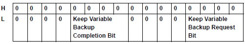
#L_BackupCmd
When you backup the data of the variables specified to be kept, it triggers backup and restore.
Bit 0: When backup is executing, the bottom 16 bits are turned OFF automatically.
Bit 1: When restore is executing, the bottom 16 bits are turned OFF automatically.
Bit 8: When backup is complete (normal completion), it is turned ON. When an error occurs, it is turned OFF.
Bit 9: When restore is complete (normal completion), it is turned ON. When an error occurs, it is turned OFF.
The other bits are reserved.
|
0
|
0
|
Restore Execution
|
Backup Execution
|
|
Bit
|
OFF
|
ON
|
|
Backup Execution
|
None
|
Request (Backup of variable)
|
|
Restore Execution
|
None
|
Request (Restore of variable)
|
After execution, it is turned OFF automatically.
When the request bits are simultaneously turned ON, restore is executed after the backup.
|
0
|
0
|
Restore Execution
|
Backup Execution
|
|
Bit
|
OFF
|
ON
|
|
Backup Execution
|
None
|
Completion Notice
|
|
Restore Execution
|
None
|
Completion Notice
|

-
You cannot backup in offline mode or transfer mode.
-
You can only restore the same project that you backed up. If it is a different project, restore will not execute.
-
When you execute backup and restore sequentially, the screen display speed may slow, or the online logic monitor may discontinue. Also, depending on the project, communication may be affected. When you allocate #L_BackupCmd to the switch parts, specify the [Bit Set] and do not touch continuously. Do not backup or restore on the D-Script using #L_BackupCmd.
-
You can back up only when Logic is stopped.