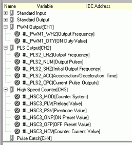
Once all the terminals are mapped in the [I/O Driver], map the standard I/O terminals in the [I/O screen]. Please note that terminals allocated to special I/O are mapped to system variables (integer format) for storing its unique information.
System variable details.
|
System Variable |
Description |
Always On |
High Speed Counter Unit |
PWM Output |
Pulse Output |
Pulse Catch |
|
Extended I/O board firmware version |
|
- |
- |
- |
- |
|
|
Special I/O control |
- |
|
|
|
|
|
|
Special output |
- |
|
|
|
- |
|
|
Change Special I/O parameter |
- |
|
|
|
- |
|
|
Special I/O parameter error |
- |
|
|
|
- |
|
|
Acceleration/Deceleration pulse table |
- |
- |
- |
|
- |
|
|
Counter input control |
- |
|
- |
- |
- |
|
|
Counter external input control |
- |
|
- |
- |
- |
|
|
Counter Input State*1 |
- |
|
- |
- |
- |
|
|
CH* Output Frequency |
- |
- |
|
- |
- |
|
|
CH* ON duty value |
- |
- |
|
- |
- |
|
|
CH* Output Frequency |
- |
- |
- |
|
- |
|
|
CH* Output pulse count |
- |
- |
- |
|
- |
|
|
CH* Initial Output Frequency |
- |
- |
- |
|
- |
|
|
CH* acceleration/deceleration time or acceleration time*1 |
- |
- |
- |
|
- |
|
|
CH* Pulse deceleration time*1 |
- |
- |
- |
|
- |
|
|
CH* Current Frequency*1 |
- |
- |
- |
|
- |
|
|
CH* Current Pulse Output Value |
- |
- |
- |
|
- |
|
|
CH* Count Method |
- |
|
- |
- |
- |
|
|
CH* Time-Base when Sampling Mode is selected*1 |
- |
|
- |
- |
- |
|
|
CH* Preload Value |
- |
|
- |
- |
- |
|
|
CH* Prestrobe Value |
- |
|
- |
- |
- |
|
|
CH* ON Preset Value |
- |
|
- |
- |
- |
|
|
CH* OFF Preset Value |
- |
|
- |
- |
- |
|
|
CH* Current Counter Value |
- |
|
- |
- |
- |
Extended I/O port firmware version (#L_ExIOFirmVer)
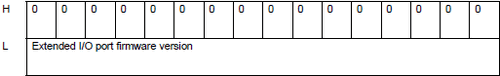
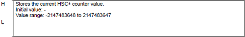
In the bottom 16 bits, stores the extended I/O board firmware version.
For "Revision 01.05," store as "0x0105."
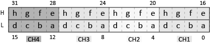
Special I/O control (#L_ExIOSpCtrl)
Checks the operation control and status of special I/O.
The bit number differs depending on the specified CH number and special I/O type.
PWM Output
|
|
Bit Number |
Feature |
Type |
Description |
Display Unit |
|
|
LT4000 |
LT3000/STC6000 |
|||||
|
a |
4(n-1)+0 |
PWM Output Control |
Control While ON |
Execute PWM output. Turn OFF to stop output. |
|
|
|
b |
4(n-1)+1 |
Forced Synchronization |
Control Up |
Resets the phase of the PWM output and output pulse. Same function as synchronize input. |
|
- |
|
c |
4(n-1)+2 |
Enable Input |
Control While ON |
Turns on the enable input function. To activate the enable function, you must turn on both this bit and the enable input signal. |
|
- |
|
d |
4(n-1)+3 |
Synchronize Input |
Control While ON |
Enables the synchronize input function. To activate the synchronize input function, you must turn on both this bit and the synchronize input signal. |
|
- |
|
e |
4(n-1)+16 |
PWM output state |
Status |
1: PWM output is being ouput. 0: PWM output is stopped. |
|
|
|
f |
4(n-1)+17 |
Forced Synchronization State |
Status |
1: Turns ON when the forced synchronization bit (b) runs forced synchronization. This bit does not turn OFF automatically. 0: Forced synchronization is stopped. |
|
- |
|
g |
4(n-1)+18 |
Enable Input Status |
Status |
1: The enable input bit (c) turns ON, and the enable input function is ready. 0: The enable input bit (c) turns OFF, and the enable input function is disabled. |
|
- |
|
h |
4(n-1)+19 |
Synchronize Input Status |
Status |
1: The synchronize input bit (c) turns ON, and the synchronize input function is ready. 0: The synchronize input bit (d) turns OFF, and the synchronize input function is disabled. |
|
- |
* To find the bit number associated with each CH, calculate by replacing "n" with the CH number.
Pulse Output
|
|
Bit Number |
Feature |
Type |
Description |
Display Unit |
|
|
LT4000 |
LT3000/STC6000 |
|||||
|
a |
4(n-1)+0 |
Pulse Output Control |
Control While ON |
1: Start output 0: Forced stop |
|
|
|
b |
4(n-1)+1 |
Acceleration/deceleration pulse settings |
Control While ON |
1: Enable 0: Disable |
|
|
|
c |
4(n-1)+2 |
Acceleration pulse settings |
Control While ON |
1: Enable 0: Disable |
|
- |
|
d |
4(n-1)+3 |
Pulse Output Direction Control |
Control While ON |
1: Negative direction (CCW) 0: Positive direction (CW) |
|
- |
|
e |
4(n-1)+16 |
Pulse Output Status |
Status |
1: Operational Slaves 0: Stopped Slaves |
|
|
|
f |
4(n-1)+17 |
Acceleration/Deceleration Pulse Settings Status |
Status |
1: Enable 0: Disable |
|
|
|
g |
4(n-1)+18 |
Pulse Count Output Completion |
Status |
1: The defined number of pulse outputs is complete. |
|
|
|
h |
4(n-1)+19 |
Pulse Output Direction |
Status |
1: Negative direction (CCW) 0: Positive direction (CW) |
|
- |
* To find the bit number associated with each CH, calculate by replacing "n" with the CH number.
High speed counter (including 2-phase counter)
|
|
Bit Number |
Feature |
Type |
Description |
Display Unit |
|
|
LT4000 |
LT3000/STC6000 |
|||||
|
a |
4(n-1)+0 |
High Speed Counter Control |
Control While ON |
1: Start count 0: Stop |
|
|
|
b |
4(n-1)+1 |
Synchronize Output |
Control While ON |
1: Enable 0: Disable |
|
|
|
c |
4(n-1)+2 |
ON Preset / OFF Preset Stop Control |
Control While ON |
1: Stop 0: Start |
|
- |
|
d |
4(n-1)+3 |
Synchronize Output Forced Control |
Control While ON |
1: Enable 0: Disable |
|
- |
|
e |
4(n-1)+16 |
High Speed Counter State |
Status |
1: Operational Slaves 0: Stopped Slaves |
|
|
|
f |
4(n-1)+17 |
Synchronize Output Setting Status |
Status |
1: Enable 0: Disable |
|
|
|
g |
4(n-1)+18 |
ON Preset / OFF Preset Stop Status |
Status |
1: Stopped Slaves 0: Operational Slaves |
|
- |
|
h |
4(n-1)+19 |
Synchronize Output Forced Control Status |
Status |
1: Enable 0: Disable |
|
- |
* To find the bit number associated with each CH, calculate by replacing "n" with the CH number.
Pulse Catch
|
|
Bit Number |
Feature |
Type |
Description |
Display Unit |
|
|
LT4000 |
LT3000/STC6000 |
|||||
|
a |
4(n-1)+0 |
Pulse Catch Clear |
Control Up |
1: Clear |
|
|
|
e |
4(n-1)+16 |
Pulse Catch Clear Status |
Status |
1: Clear Complete |
|
|
|
f |
4(n-1)+17 |
Pulse Catch Detect |
Status |
1: Has input 0: No input |
|
|
|
g |
4(n-1)+18 |
Input Terminal Current Status |
Status |
1: ON 0: OFF |
|
- |
* To find the bit number associated with each CH, calculate by replacing "n" with the CH number.
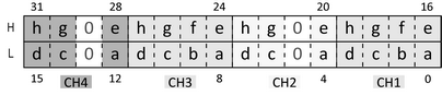
Special I/O output (#L_ExIOSpOut)
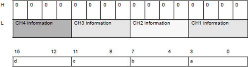
This variable uses the CH specified in the I/O driver settings as the 4-bit configuration information to show the special I/O output state.
a: CH1 special I/O output state
b: CH2 special I/O output state
c: CH3 special I/O output state
d: CH4 special I/O output state
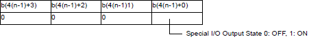
* Apply the CH number to "n" to find the corresponding bit number "b".
![]()
With the LT4000 Series, the output status using #L_ExIOSpOut can only be confirmed with the high speed counter's synchronize output. To confirm other special I/O ouput status, use #L_ExIOSpCtrl.
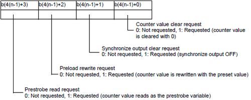
Special I/O parameter change (#L_ExIOSpParmChg)
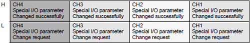
Request Special I/O Parameter Change

This variable uses the CH specified in the I/O driver settings as the 4-bit configuration information to request the special I/O parameter change.
a: CH1 special I/O parameter change request
b: CH2 special I/O parameter change request
c: CH3 special I/O parameter change request
d: CH4 special I/O parameter change request
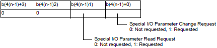
* Change the parameter before turning the bit on for the special I/O parameter change request.
* You cannot change the parameter for the acceleration/deceleration pulse here. Use a table creation request flag for the acceleration/deceleration pulse.
* When reading the parameter of the acceleration/deceleration pulse, turn on the flag for the acceleration/deceleration pulse to control the special I/O operation.
* Apply the CH number to "n" to find the corresponding bit number "b".
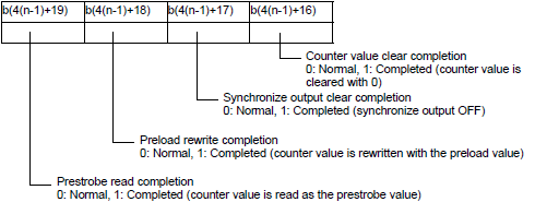
Special I/O parameter change completed

This variable uses the CH specified in the I/O driver settings as the 4-bit configuration information to notify the completion of the special I/O parameter change.
a: CH1 special I/O parameter changed successfully
b: CH2 special I/O parameter changed successfully
c: CH3 special I/O parameter changed successfully
d: CH4 special I/O parameter changed successfully
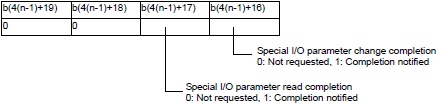
* Apply the CH number to "n" to find the corresponding bit number "b".
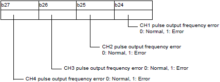
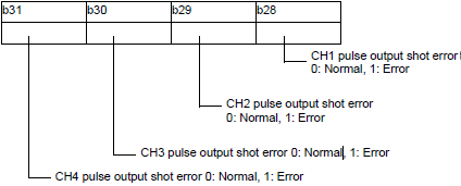
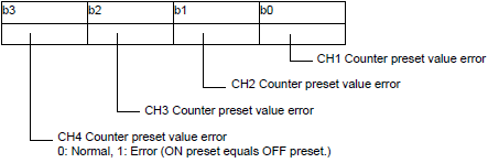
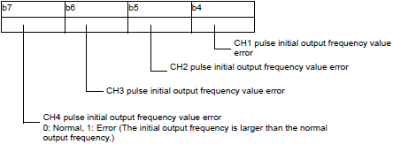
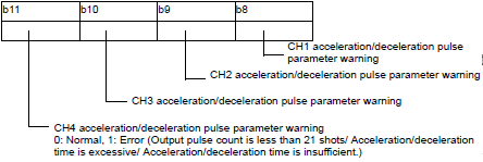
Special I/O parameter error (#L_ExIOSpParmErr)
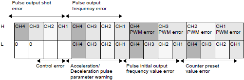
The applicable bit turns ON if there is an error when the parameter changes to a special I/O parameter.
PWM error
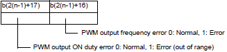
* Apply the CH number to "n" to find the corresponding bit number "b".
Pulse output frequency error
Pulse output shot error
Counter preset value error
Pulse initial output frequency value error
Acceleration/Deceleration pulse parameter warning
Control error
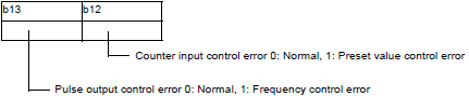
Counter input control error occurs when the bottom 16 bits in the ON Preset Value or OFF Preset Value is xxxxFFFFh or xxxx0000h.
* The pulse output control error occurs when the total of the Counter Input condition check time and Pulse Output condition check time exceed the minimum width for the Pulse Output.
For details, see 31.5.14 Restrictions.
Acceleration/Deceleration pulse table control (#L_ExIOAccelPlsTbl)
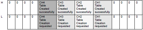
Request for the acceleration/deceleration pulse table creation

|
a: CH1 acceleration/deceleration pulse table creation request |
0: Not requested, 1: Requested |
|
b: CH2 acceleration/deceleration pulse table creation request |
0: Not requested, 1: Requested |
|
c: CH3 acceleration/deceleration pulse table creation request |
0: Not requested, 1: Requested |
|
d: CH4 acceleration/deceleration pulse table creation request |
0: Not requested, 1: Requested |
The Create Acceleration/Deceleration table complete successfully

a: CH1 acceleration/ deceleration pulse table created successfully
b: CH2 acceleration/ deceleration pulse table created successfully
c: CH3 acceleration/ deceleration pulse table created successfully
d: CH4 acceleration/ deceleration pulse table created successfully
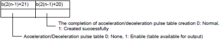
* Apply the CH number to "n" to find the corresponding bit number "b".
Counter Input Control (#L_ExIOCntInCtrl)
Control request for counter input only

This variable uses the CH specified in the I/O driver settings as the 4-bit configuration information to request the counter input control.
a: CH1 counter input control request
b: CH2 counter input control request
c: CH3 counter input control request
d: CH4 counter input control request
* Apply the CH number to "n" to find the corresponding bit number "b".
Counter input control response

This variable uses the CH specified in the I/O driver settings as the 4-bit configuration information to store the counter input control response.
a: CH1 counter input control response
b: CH2 counter input control response
c: CH3 counter input control response
d: CH4 counter input control response
* Apply the CH number to "n" to find the corresponding bit number "b".
Counter External Input Control (#L_ExIOCntInExtCtrl)
System variable to control and check the status of the extended input (preload/prestrobe/marker) for high-speed counter and 2-phase counter.
|
|
Bit Number |
Feature |
Type |
Description |
Display Unit |
|
|
LT4000 |
LT3000/STC6000 |
|||||
|
a |
4(n-1)+0 |
Preload/prestrobe operation complete |
Control Up |
Turns ON when you use the preload/prestrobe input as the trigger and write the preload/prestrobe value to the current value. This bit turns OFF when you turn ON the preload/prestrobe completion acknowledged bit (e). |
|
|
|
b |
4(n-1)+1 |
2-phase counter input marker completion |
Control Up |
Turns ON when you use the marker input as the trigger and write the marker value to the current value. This bit turns OFF when you turn ON the 2-phase counter input marker completion acknowledged bit (f). |
|
|
|
c |
4(n-1)+2 |
High Speed Counter Control |
Control While ON |
1: Start count 0: Stop |
|
- |
|
d |
4(n-1)+3 |
Allow Extended Input |
Control While ON |
Enables extended input function (external input). To activate extended input, turn ON this bit. |
|
- |
|
e |
4(n-1)+16 |
Preload/prestrobe completion acknowledged |
Control Up |
Confirm the preload/prestrobe operation complete bit (a) is ON, and then turn ON this bit. |
|
|
|
f |
4(n-1)+17 |
2-phase counter input marker completion acknowledged |
Control Up |
Confirm the 2-phase counter input marker operation complete bit (b) is ON, and then turn ON this bit. |
|
|
|
g |
4(n-1)+18 |
High Speed Counter State |
Status |
1: In operation 0: Stopped |
|
- |
|
h |
4(n-1)+19 |
Extended Input Status |
Status |
1: Enable external input 0: Disable |
|
- |
* To find the bit number associated with each CH, calculate by replacing "n" with the CH number.
Counter input state (#L_ExIOCntInState)
Shows the input satus of the high speed counter. The bit to be used is determined by the CH number set with the high speed counter in the I/O driver settings.
|
|
Bit Number |
Feature |
Type |
Description |
Display Unit |
|
|
LT4000 |
LT3000/STC6000 |
|||||
|
a |
4(n-1)+0 |
Clear reached flag |
Control Up |
Turn OFF the reached Upper/Lower limit flag (e). |
|
- |
|
e |
4(n-1)+16 |
Reached Upper/Lower limit flag |
Status When condition is satisfied |
When the counter mode is [Ring] or [Linear], and the current value reaches the upper or lower limit, the flag turns ON. Condition: Current Counter Value = Upper Limit (Lower Limit) |
|
- |
|
f |
4(n-1)+17 |
Comparison with preset value (smaller) |
Status While condition is satisfied |
Turns ON when the current value is greater than the smaller preset value. Up Count Condition: Preset Value (smaller) <= Current Counter Value |
|
- |
|
g |
4(n-1)+18 |
Comparison with preset value (larger) |
Status While condition is satisfied |
Turns ON when the current value is greater than the larger preset value. Up Count Condition: Preset Value (larger) <= Current Counter Value |
|
- |
|
h |
4(n-1)+19 |
Comparison with preset value (larger/smaller) |
Status While condition is satisfied |
Turns ON when the current value is between the ON preset value and OFF preset value. Up Count Condition: Preset Value (smaller) <= Current Counter Value < Preset Value (larger) |
|
- |
* To find the bit number associated with each CH, calculate by replacing "n" with the CH number.
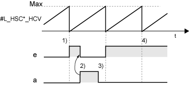
a,e: Upper/Lower limit reached flag and clear bit
The following explains the actions of the upper/lower limit reached flag (e) and Clear bit (a).
The counter mode is [Ring], and the counter operation is [Up Count].
|
|
#L_HSC*_HCV: Current Counter Value
e: Reached Upper/Lower limit flag a: Clear bit for the reached flag |
1) When current counter value (#L_HSC*_HCV) reaches the upper limit, the upper/lower limit reached flag (e) turns ON.
2) When the reached flag's clear bit (a) is turned ON, the upper/lower limit reached flag (e) turns OFF.
3) The reached flag's clear bit (a) turns OFF.
4) While the upper/lower limit reached flag (e) is ON, the current counter value (#L_HSC*_HCV) reaching the upper limit cannot be detected.
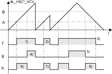
f,g,h: Compare the preset value and current counter value
You can determine if the current counter value is greater than or less than the preset value by comparing them.
There are two preset values: ON preset value and OFF preset value. Bit "f" stores the comparison result with the smaller preset value. "g" stores the comparison result with the larger preset value.
|
|
#L_HSC*_HCV: Current Counter Value B: Preset Value (large) A: Preset Value (smaller)
f: Comparison with preset value (smaller) g: Comparison with preset value (larger) h: Comparison with preset value (larger/smaller) |
f. Comparison with Preset Value (smaller)
1) At up count, when the current counter value (#L_HSC*_HCV) reaches "A", "f" turns ON. When the current counter value reaches the upper limit and resets, "f" turns OFF.
2) When the current counter value reaches "A" again, "f" turns ON. When the current counter value is reset while counting, "f" turns OFF.
3) At down count, when the current counter value reaches "A", "f" turns OFF.
g. Comparison with Preset Value (larger)
4) At up count, when current counter value (#L_HSC*_HCV) reaches "B", "g" turns ON. When current value reaches the upper limit and is reset, "g" turns OFF.
5) At down count, when the current counter value reaches "B", "g" turns OFF.
h. Comparison with Preset Value (larger/smaller)
6) At up count, when the current counter value (#L_HSC*_HCV) reaches "A", "h" turns ON. When the current value reaches "B", "h" turns OFF.
7) While bit "h" is ON, if the current counter value exceeds the range defined by A and B, "h" turns OFF.
8) At down count, if the current counter value reaches "B", "h" turns ON. If it reaches "A", "h" turns OFF.
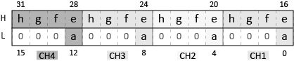
CH* Output Frequency (#L_PWM*_WHZ)
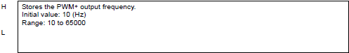
CH* ON duty value (#L_PWM*_DTY)
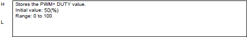
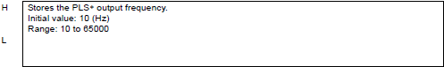
CH* Output Frequency (#L_PLS*_LHZ)
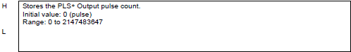
CH* Output pulse count(#L_PLS*_NUM)
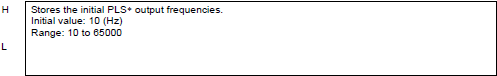
CH* Initial Output Frequency (#L_PLS*_SHZ)
CH* acceleration/deceleration time (#L_PLS*_ACC)
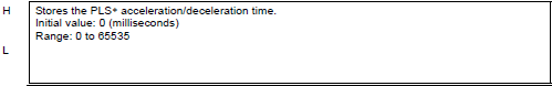
![]()
When using the LT4000 Series, #L_PLS*_ACC specifies the acceleration time.
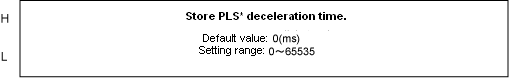
CH* Pulse deceleration time (#L_PLS*_DEC)
CH* Current Frequency (#L_PLS*_CHZ)
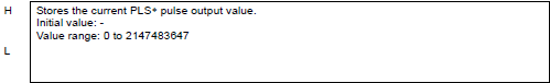
CH* Current Pulse Output Value (#L_PLS*_CPC)
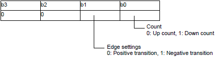
CH* Count Method (#L_HSC*_MOD)
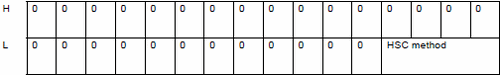
HSC method
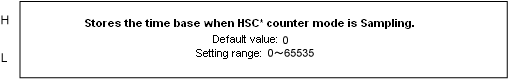
CH* time-base in event mode (#L_HSC*_TB)
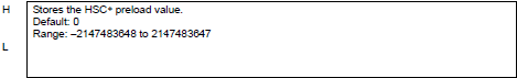
CH* Preload Value (#L_HSC*_PLV)
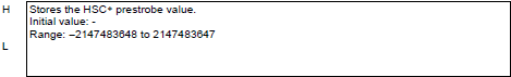
CH* Prestrobe Value (#L_HSC*_PSV)
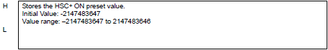
CH* ON Preset Value (#L_HSC*_ONP)
CH* OFF Preset Value (#L_HSC*_OFP)
CH* Current Counter Value (#L_HSC*_HCV)