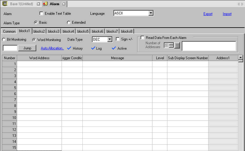
Word Monitoring
An alarm is triggered when the value of the monitoring word address matches with the specified alarm value, or is within the specified alarm range.
Data Type
Choose the data format of the value stored in [Word Address] from [Dec], [Hex], or [BCD].

-
When the [Data Type] is changed during editing, the data (alarm value) which cannot be converted into the new [Data Type] will become "0".
Example:
Dec 10 → Hex 000A
Dec 10 → BCD 0 (unable to convert, displays as 0)
Sign +/-
Select this if you will be using negative data for the alarm value. This can only be set when the [Data Type] is [Dec].
Jump
Go to a specific row number.
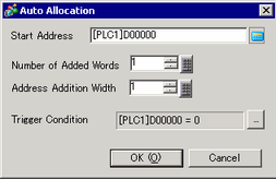
Auto Allocation
The [Address Auto Allocation] dialog box appears. Configure settings to allocate addresses from the [Start Address] by specified increments.
-
When a previous address exists, it will be overwritten.
Start Address
Set the Word Address that will start the Auto Allocation.
Number of Added Words
Set the number of Word Addresses (from 1 to Alarm limit - Current row position + 1) for Auto Allocation.
Increase Address By
Set the number of Words to add during an Auto Allocation, from 0 to 4,096.
Trigger Condition
Set the condition that triggers the alarm.  Click the icon to display the [Trigger Condition Settings] dialog box.
History/Log/Active
Displays current display mode set in the [Common] tab.
 20.12.1.1 Common Settings (Alarm) Settings Guide
Number of Units
When [Alarm Type] is set to [Extended], set the number of units from 1 to 256. Depending on the specified number of units, a rung for setting the Monitoring Address will be added. You can specify separate Monitoring Addresses for multiple units of the same message.
Polling Frequency
When [Alarm Type] is set to [Extended], set the polling frequency to read the Alarm Monitoring Address. You cannot read the monitoring address right after starting up the display unit. Reading the address starts when the defined polling frequency elapses.
-
When a read operation is started, read requests for the same block are not accepted until all addresses have been read.
-
If multiple requests to read blocks at the same time, read from the small number of blocks.
-
If the state of the Monitoring Address changes during a read operation, it will be read during the following polling frequency. Trigger Time/Acknowledged Time/Recovery Time uses the time when data was read, not the time when the monitoring address was changed.
-
If there is a read request from a separate block during a read operation, the block with the earliest request will be read starting immediately before the current read operation is completed.
-
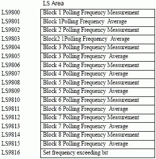
The Polling Frequency's actual value (in seconds) and the average value (in seconds) are stored, block by block, in the following internal device addresses. Also, if the actual value exceeds the defined polling frequency even once, the defined range frequency exceeded bit is set ON. Once the bit is set ON, it will not turn OFF, even if the actual values are under the polling frequency. You need to turn the bit OFF manually.
-
The format for the set frequency exceeding bit is as follows.
|
LS9816
|
Bit
|
Details
|
|
0
|
Block 1 Exceeding Bit
|
|
1
|
Block 2 Exceeding Bit
|
|
2
|
Block 3 Exceeding Bit
|
|
3
|
Block 4 Exceeding Bit
|
|
4
|
Block 5 Exceeding Bit
|
|
5
|
Block 6 Exceeding Bit
|
|
6
|
Block 7 Exceeding Bit
|
|
7
|
Block 8 Exceeding Bit
|
|
8...15
|
Reserved
|
-
Polling Frequency may not keep the set time due to a load condition in the environments.
In the actual run-time environment, check the frequency Exceeding Bit and Polling Frequency Measurement, then adjust the alarm monitoring address's holding time accordingly.
-
If no data was read because of a communication error, the data will be read at the next Polling Frequency.
Read Data From Each Alarm
Specifies whether or not Alarm message data is read.
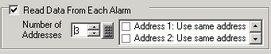
Number of Addresses
Read data values from 1 to 8. Adds the [Common Address] setting rows to the set number of addresses. The address setting column will be available for input in the Alarm List.
Use Same Address
Sets whether or not address data values are read in all the messages in the block regardless of the Alarm Message. In the address setting column, you cannot set anything from the second row onward.
Number
Displays the Alarm Message registration number (Row Number).
Unit Name
When [Alarm Type] is set to [Extended], the number of units set in [Number of Units] is inserted. Unit names can be specified up to 32 single-byte characters. You can also use data from the Text Table. When an alarm occurs, the Unit Name + Message is displayed as the Alarm Message.
-
When using the Text Table data, if line feed is inserted in the data, the text before the line feed will be displayed as a unit name. The text after the line feed will not be displayed.
-
Even if the text table data has multiple lines or more than 32 characters, only up to 32 characters for a unit name can be displayed per line.
Word Address
Set the Word Address to monitor the alarm's trigger.
Trigger Condition
Set the alarm value that will trigger the alarm. In the cell, click  and the [Trigger Condition] dialog box appears.
-
When you set the Alarm Value to zero, at the startup the alarm is not triggered even if the Monitoring Word Address is zero. However, as soon as the Monitoring Word Address changes from non-zero to zero, the alarm is triggered. The same condition applies when the system recovers from the offline mode or when you transfer a project, unless you save the history to the backup memory (SDRAM).
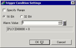
16 bit/32 bit
Choose the alarm value bit length from [16 Bit] or [32 Bit].
Alarm Value
Select which range of values stored in the monitoring Word Address will trigger the alarm. The set range varies depending on the [Data Type] and [Sign +/-].
|
Bit Length
|
Data Type
|
Sign +/-
|
Setting Range
|
|
16 bit
|
Dec
|
Enable
|
-32768...32767
|
|
Disable
|
0...65535
|
|
Hex
|
-
|
0...FFFF
|
|
BCD
|
-
|
0...9999
|
|
32 bit
|
Dec
|
Enable
|
-2147483648...2147483647
|
|
Disable
|
0...4294967295
|
|
Hex
|
-
|
0...FFFFFFFF
|
|
BCD
|
-
|
0...99999999
|
Specify Range
Select whether or not to set a range for the alarm value. The display will change as follows.
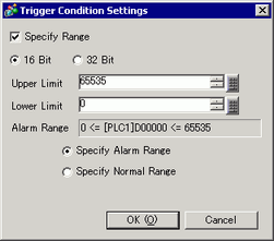
Upper Limit, Lower Limit
Select which range of values stored in the monitoring Word Address will trigger the alarm. The set range varies depending on the [Data Type] and [Sign +/-].
|
Bit Length
|
Data Type
|
Sign +/-
|
Setting Range
|
|
16 bit
|
Dec
|
Enable
|
-32768...32767
|
|
Disable
|
0...65535
|
|
Hex
|
-
|
0...FFFF
|
|
BCD
|
-
|
0...9999
|
|
32 bit
|
Dec
|
Enable
|
-2147483648...2147483647
|
|
Disable
|
0...4294967295
|
|
Hex
|
-
|
0...FFFFFFFF
|
|
BCD
|
-
|
0...99999999
|
Alarm Range
It displays the specified alarm range.
Specify Alarm Range/Specify Normal Range
Set the alarm range as "Lower Limit <= Address Value <= Upper Limit".
Set the alarm range as "Lower Limit >= Address Value" or "Address value >= Upper Limit".
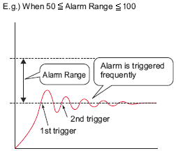
-
If the alarm value stored in the [Word Address] fluctuates frequently, the alarm will be triggered often.
Message
Set an alarm message within 160 single-byte characters.
-
When [Enable Text Table] is not selected, you can insert up to 5 lines by typing [Alt]+[Enter].
-
If an alarm part is set to [Show History] with the [Message Display Method] set to [Multiple line display], and [Enable Text Table] is selected in the alarm editor, the message displays using the text table's index character number. The alarm message can be up to 5 lines long. If the message is longer than 5 lines, only the first 5 lines will display.
-
If an alarm part is set to [Show History] with the [Message Display Method] set to [1 Line display], and the message uses text table data which uses line feeds, only text before the line feed displays as the message. Text after the line feed will not display.
-
When using the GP-4100 series (Monochrome Model), you cannot enter multiple lines. When importing alarm settings and there are multiple line messages, only the first row is imported.
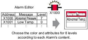
Level
Each Alarm Message is ranked by importance from 0 (least important) to 7 (most important). The initial setting is "0". The Trigger, Acknowledged, and Recovery colors for each level can be set with the Alarm Part.
20.12.2.5 Show History - Color Settings
Group
This item is displayed only when [Enable the Group feature] is selected in the Common Settings. Set a group number to each alarm message within the range between 0 and 6096.
20.12.1.1 Common Settings (Alarm) Settings Guide
-
When the [Group Number] is "0", it will not count.
Sub Display Screen Number
When using an Alarm part for a Sub Display, select the desired Base Screen Number from 0 to 9999, or the Text File Number from 0 to 8999. Specify the Index numbers of the play list file for playing movies.
-
If no Sub Display is required, enter "0". The initial setting is "0".
-
If the specified text screen number does not exist, a window without text will be displayed in the display unit.
Addresses 1 to 8
Sets Addresses to read Alarm Message data. The input rows become available for the addresses specified in [Number of Addresses].
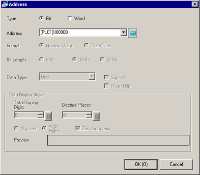
Type
Select the address type from either [Bit] or [Word].
Address
Sets read data addresses.
-
You can set an external device/PLC address, an internal address, a symbol variable, and a system variable for a Bit Address.
Data Class
If you have set the [Type] to [Word], select the data class stored in the address from [Numeric Value] or [Date/Time].
Numeric Value
Bit Length
Select the data bit length from [8 Bit], [16 Bit] or [32 Bit].
Data Type
Select the data format of the value stored in the address from [Dec], [Hex], [BCD] or [Float]. You can only select [Float] when the [Bit Length] is set to [32 Bit].
Sign +/-
Use for negative numbers. This can only be set when the [Data Type] is [Dec].
Round Off
Select whether or not fractional values will be rounded off when data is displayed. Numbers are truncated if not rounded. This setting is available when [Data Type] is [Float].
Total Display Digits, Decimal Places
Specify digits for display values from 1 to 11. When selecting [Float], the range of the digits is from 1 to 17. "Total Display Digits -1" is the maximum range for the number of digits after the decimal point. The range depends on [Bit Length] and [Data Type].
|
Bit Length
|
Data Type
|
Total Display Digits
|
Decimal Places
|
|
Setting Range
|
|
8 bit
|
Dec
|
1...11
|
0...10
|
|
Hex
|
1...11
|
-
|
|
BCD
|
1...11
|
0...10
|
|
16 bit
|
Dec
|
1...11
|
0...10
|
|
Hex
|
1...11
|
-
|
|
BCD
|
1...11
|
0...10
|
|
32 bit
|
Dec
|
1...11
|
0...10
|
|
Hex
|
1...11
|
-
|
|
BCD
|
1...11
|
0...10
|
|
Float
|
1...17
|
0...16
|
Align Left/Align Right
Select the display position of a value from [Align Left] or [Align Right].
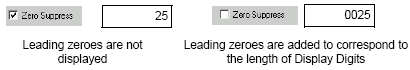
Zero Suppress
If this option is selected, leading zeros are not displayed.
For example, Number of Display Digits = 4
Preview
Displays the data image according to the settings.
Date/Time
Data Type
Select the data type of [Date/Time] from [TIME], [DATE], or [TIME_OF_DAY].
Timer
Select the timer item to display.
Displayed when [TIME] is selected at [Data Type].
Date
Specify whether or not to display a date. If so, select the date item to display.
This appears when [Data Type] is set to [DATE].
Day of the Week
Specify whether to display a day of the week.
This appears when [Data Type] is set to [DATE].
Time of day
Select if you want to display the time of day.
This appears when [Data Type] is set to [TIME_OF_DAY].
Format
Select the display format the [Timer], [Date], or [Time of Day].
Number of Digits
Set the number of digits for the first item in the display format. Select the display format at the [Format].
Displayed when [TIME] is selected at [Data Type].
Align Left/Align Right
Select the display position from [Align Left] or [Align Right].
Preview
Displays the data image according to the settings.