![]()
Please refer to the Settings Guide for details.
 5.18.2 New Settings Guide
5.19.1 Display Settings Guide
![]()
Please refer to the Settings Guide for details.
![]() 5.18.2 New Settings Guide
5.18.2 New Settings Guide
![]() 5.19.1 Display Settings Guide
5.19.1 Display Settings Guide
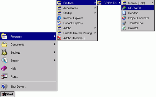
Double-click the shortcut on the desktop ![]() , or from the [Start] menu, point to [Programs (P)], then [Pro-face], and select [GP-Pro EX *.**]. The asterisks** define the version number.
, or from the [Start] menu, point to [Programs (P)], then [Pro-face], and select [GP-Pro EX *.**]. The asterisks** define the version number.
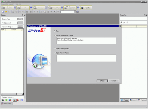
GP-Pro EX opens and the screen appears as below.

The [Welcome to GP-Pro EX] dialog box appears. Select [New] and click [OK].
![]()
To create a new project, from the [Project (F)] menu, select [New (N)]. You can also click the ![]() , to create a new project. The [Welcome to GP-Pro EX] dialog box appears.
, to create a new project. The [Welcome to GP-Pro EX] dialog box appears.
You can create a project file based on sample projects stored in the [Sample] folder. In the welcome dialog box, select [Create Project from Sample]. The project will be read-only. Save the file using the [Project (F)] menu's [Save As (A)] command.
In the next screen, from [Series] select [GP3000 Series], and then select the screen size series, [Model] and [Orientation]. Then click [Next].![]() 3.3 Supported Model List
3.3 Supported Model List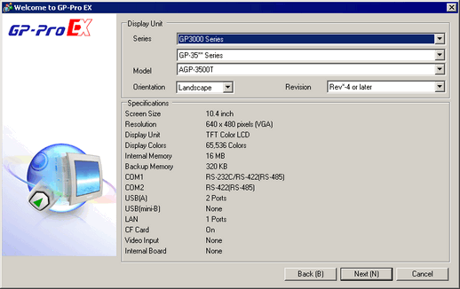
![]()
[Specifications] shows the detailed specifications of the selected display model.
If you select [GP2000 Series], GP-Pro EX exits and GP-PRO/PBIII for Windows starts. GP-PRO/PBIII does not start if not installed.
When you select the [IPC Series (PC/AT)], you do not need to set [Orientation]. Specify the data display size in [Screen Size].
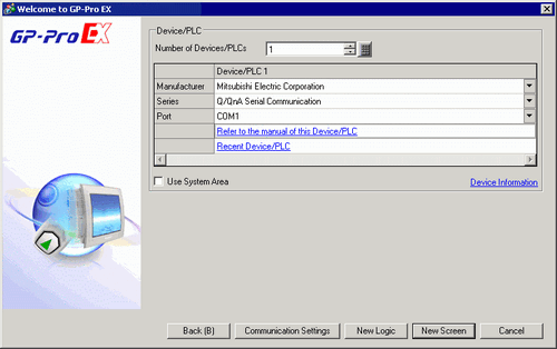
The following dialog box appears. Select [Manufacturer], [Series], and [Port], and then click [Communication Settings].
![]()
To create a screen without configuring communication settings for the device/PLC series, click [New Screen]. The screen editor will display [Base 1].
To create a logic program, click [New Logic] to display the logic editor [Main].![]() Chapter 29 Logic Programming
Chapter 29 Logic Programming
If you select the [Use System Area] check box, you can set up the display unit's internal system data area on the device/PLC.![]() 5.19.6 Display Unit (System Area) Settings Guide
5.19.6 Display Unit (System Area) Settings Guide
When the [New Project File] dialog box closes and the [Peripheral List] appears in the main window. Click [Device/PLC1].
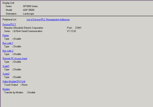
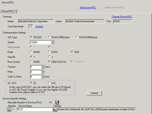
When [Device/PLC] is displayed, specify the communication settings.
![]()
The [Communication Settings] details differ depending on the device/PLC series. See the "GP-Pro EX PLC/Device Connection Manual" for your device/PLC.
It is recommended to keep the default settings for [Timeout], [Retry], and [Wait to Send].
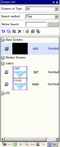
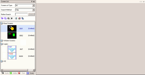
Open the Screen List window and double-click the base screen.
![]()
If the [Screen List] is not on the workplace, from the [View (V)] menu, point to [Work Space (W)] and select [Screen List (G)].
To create a logic program, double-click the logic screen currently displayed. If you select a model that does not support the logic features, you can create the logic program but the program will not run on the display.![]() Chapter 29 Logic Programming
Chapter 29 Logic Programming
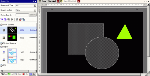
The [Base Screen] displays, as shown.
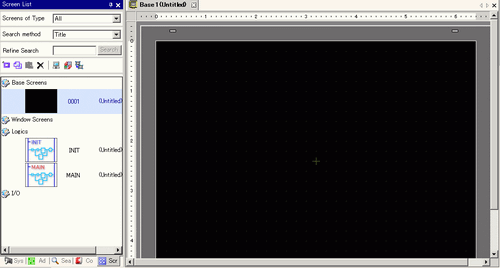
Create a screen.
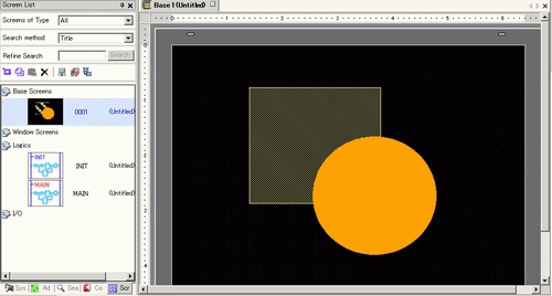
Add a new screen.
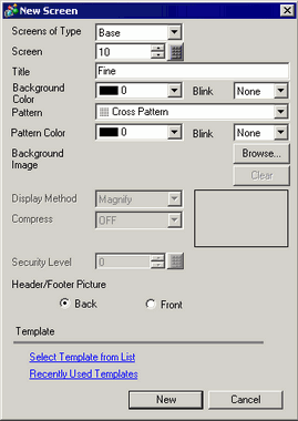
From the [Screen (S)] menu, select [New Screen (N)] or click ![]() . The [New Screen] dialog box appears. Select the [Screens of Type], specify the screen number and [Title] then click [New].
. The [New Screen] dialog box appears. Select the [Screens of Type], specify the screen number and [Title] then click [New].
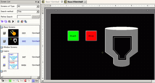
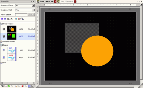
[Base 2] appears.
![]()
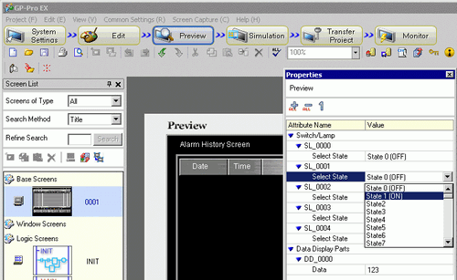
You can check the display state of the screen, even during drawing mode, by clicking the [Preview] icon![]() on the State toolbar. (Colors display by using the display unit's color settings). You can preview the Base and Window screens only.
on the State toolbar. (Colors display by using the display unit's color settings). You can preview the Base and Window screens only.
From the [View (V)] menu, point to [Workspace (W)] and select [Properties (P)] to check simple operations (for example, show or hide Window parts, change the state of Switch Lamps, and display values in Data Displays).
You can save the displayed preview screen to a JPEG file by selecting [Export to File (F)] from the [Screen Capture (C)] menu.
After confirming the display, click the [Edit] icon ![]() on the State tool bar to return to the screen editor.
on the State tool bar to return to the screen editor.
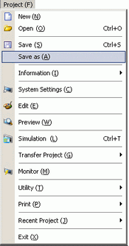
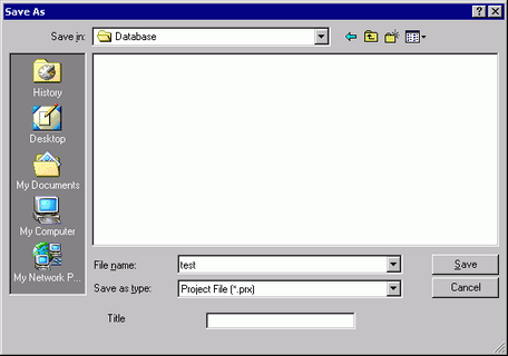
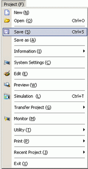
From the [Project (F)] menu, select [Save As (A)].
The [Save As] dialog box appears. Define the storage location and file name and click [Save].
![]()
Your file name can contain up to 255 characters, including the file extension.
The default location is \Program Files\Pro-face\GP-Pro EX *.**\Database.
The following error message is displayed in the [Error Check] window if there is a problem saving the file.
![]() 33.9 Checking Errors
33.9 Checking Errors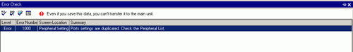
Modifying
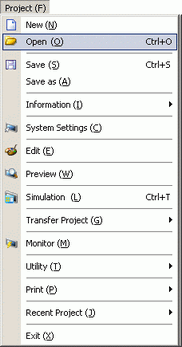
From the [Project (F)] menu, select [Open (O)] or click the Open icon ![]() .
.
![]()
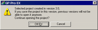
If you attempt to open a project file from a previous version, the following warning message appears.
Project files copied or transferred to CD-ROM will open as read-only. When saved, the [Save as] dialog box appears, where you can change the file name.
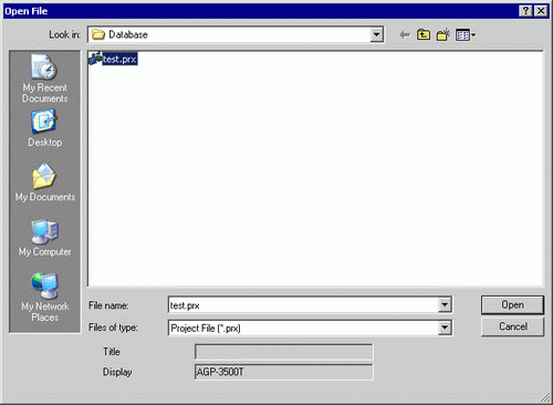
In the [Open File] dialog box, specify the project file(*.prx), then click [Open].
The project's main window opens.
![]()
You can also open a project file by directly double-clicking the project file (*.prx).
You can open two different project files at the same time.
From the [Screen List] window, select the Base Screen you want to modify. The screen appears in the editing area.
![]()
From the [Screen List] window, select the logic screen you want to modify. The screen appears in the editing area.
Modify the screen.
To save the changes, from the [Project (F)] menu, select [Save (S)] or click the Save icon ![]() .
.
Finishing
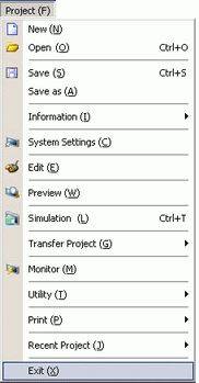
To close the project, from the [Project (F)] menu, select [Exit (X)] or click the![]() icon in the top right corner.
icon in the top right corner.
![]()
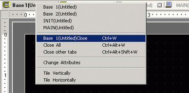
To close a screen, click ![]() on the right-side of the screen tab, or right-click the tab and from the menu select [Close (Screen Number)]. You can also close it with the shortcut key.
on the right-side of the screen tab, or right-click the tab and from the menu select [Close (Screen Number)]. You can also close it with the shortcut key.
The tab display is saved when you close the project. The next time you open the project, the tab display will be the same as when you exited.
If you change a project file and try to exit the application without saving it, the [Confirm Project File Save] dialog box appears.
If you click [Yes (Y)], the project is saved in the current state and closed.
If you click [No (N)], the project closes with the last saved information.
If you click [Cancel], the project returns to the state before the operation without being closed.