![]()
Please refer to the Settings Guide for details.
 10.15.1 Bit Switch
7.7 Settings GuideFor details on how to draw parts, and defining the address, shape, color, and labels, please see the parts editing topic.
8.6.1 Editing Parts
![]()
Please refer to the Settings Guide for details.![]() 10.15.1 Bit Switch
10.15.1 Bit Switch
![]() 7.7 Settings Guide
7.7 Settings Guide
For details on how to draw parts, and defining the address, shape, color, and labels, please see the parts editing topic.![]() 8.6.1 Editing Parts
8.6.1 Editing Parts
Create a touch switch to reverse the ON/OFF bit address that controls each device/PLC's communication scan.
On the [Parts (P)] menu, point to [Switch Lamp], and select [Bit Switch (B)], or click ![]() to place a switch on the screen.
to place a switch on the screen.
Double-click the placed Switch part. The following dialog box appears.
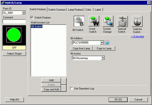
In [Select Shape], select the Switch shape.
In [Bit Address], set the address to start and stop communication scans.
![]()
Use the internal device address LS9550 - LS9557 to control the start or stop of the communication scan.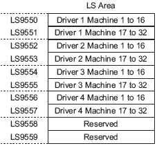
For example,
You can control up to 16 communication scans for Driver1 using LS9550.
[LS9550]![]()
Bit 0: Turns scans ON/OFF for Driver1's first PLC.
Turning ON bit 0 stops the scan of the first device/PLC controlled by Driver 1. Turn OFF Bit 0 to resume the scan.
You cannot stop the communication scan of a device specified with the System Area Start Address. However, if you are not using the System Data Area, you can stop the communication scan.![]() 5.19.6 Display Unit (System Area) Settings Guide
5.19.6 Display Unit (System Area) Settings Guide
If you designate a 32-bit device in [System Area Start Address], you can set 32 bits in the LS area. However, you can use only the lower 16 bits to control the communication scan.
When you turn OFF the communication scan, the displayed device/PLC data will remain. However, if you change screens and then display the screen again, the device/PLC data will not be displayed.
From [Bit Action], choose [Bit Invert].
As needed, set the color and display text on the [Color] tab and [Label] tab, and click [OK].
![]()
Depending on the shape, you may not be able to change the color.
When you select a switch and press the [F2] key, you can directly edit the text on the label.