From the [Parts (P)] menu, point to [Switch Lamp (C)] and select [Lamp (L)] or click ![]() .
.
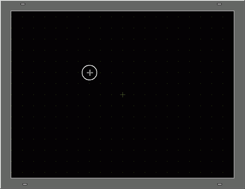
![]() Move the pointer to the drawing screen and the pointer changes to a cross-hair cursor
Move the pointer to the drawing screen and the pointer changes to a cross-hair cursor ![]() .
.
Drag the switch to the desired location. Release to place the switch.
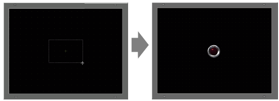
![]()
You can also drag and drop a part from the Parts Toolbox.
From the [View (V)] menu, point to [Work Space (W)] and then click [Parts Toolbox (T)]. In the Parts Toolbox, select the [Parts Palette] and [Type] to browse various parts and shapes.![]() 5.18.5.9 Parts Toolbox
5.18.5.9 Parts Toolbox
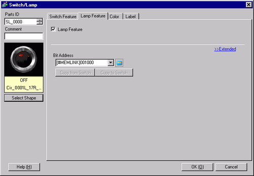
Double-click the placed lamp. The Switch/Lamp dialog box appears.
![]() Click the icon to display the [Input Address] dialog box.
Click the icon to display the [Input Address] dialog box.
![]() Click the icon and select the [Device/PLC] and [Device]. Input the address from the keypad.
Click the icon and select the [Device/PLC] and [Device]. Input the address from the keypad.
![]()
Input the address with the keypad on the Input Address dialog. If you input it directly with the PC keyboard, it may not be recognized as an address.
Select the [Use as Default Value] check box and click [Ent], and the value registered as the default value in the [Address Input] dialog box will appear on the next time.
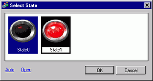
Click [Select Shape].
The [Select State] dialog box appears. Select [State 0] and click [Open].
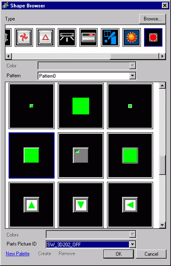
Select "SW_3D202_OFF" from [Parts Picture ID].
![]()
By changing [Type], you can select various types of images. There are parts with 65536, 256 or 64 colors. Please select the part palette that matches the colors supported by your model.
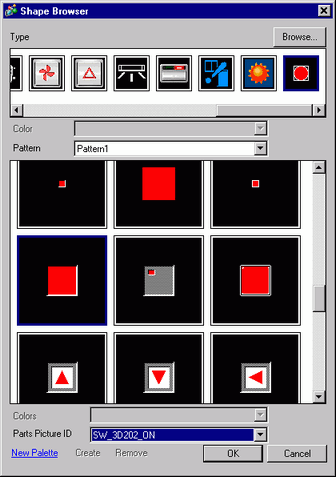
Click [OK] and the display returns to the [Select State] window. Select [State 1] and click [Open].
Select "SW_3D202_ON" from [Parts Picture ID].
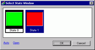
The pictures at [State 0] (OFF) and [State 1] (ON) are displayed. Click [OK].
![]()
Click [Auto] after defining the picture in [State 0] to automatically match the pictures for all other states with [State 0].
If different states have different shapes, part of a previous shape may remain in the background when touching the switch to change its state. This results because part shapes are drawn by overwriting the other.
Click the [Color] tab. Confirm that [Select State] is OFF and set the color of the switch for the OFF state. For the [Display Color], click ![]() and select a color from the color palette.
and select a color from the color palette.
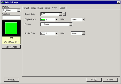
![]()
You cannot edit the color for the Switch/Lamp menu image parts.
To change the palette in the color code order, click the color code button under the palette.
Click ![]() in [Select State] to select ON, and set the color of the switch for the ON state.
in [Select State] to select ON, and set the color of the switch for the ON state.
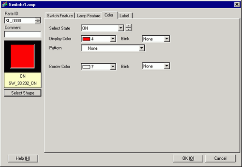
![]()
You cannot edit the color for the Switch/Lamp menu image parts.
To change the palette in the color code order, click the color code button under the palette.
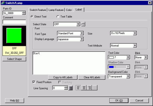
Select the [Label] tab. Click ![]() in [Select State] to select OFF, and input the text to display on the switch in the OFF state.
in [Select State] to select OFF, and input the text to display on the switch in the OFF state.
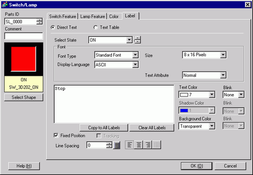
Click ![]() in [Select State] to select ON, and input the text to display on the switch in the ON state.
in [Select State] to select ON, and input the text to display on the switch in the ON state.
![]()
Select the switch and press [F2] key, and you can directly edit the text on the label.
Click [OK] when all the settings are complete.