![]()
Please refer to the Settings Guide for details.
 16.4.1 Input Equipment (Bar Code 1/Bar Code 2) Settings
Configure settings to store the code data read from a two-dimensional code reader from LS20 in the display unit.
![]()
Please refer to the Settings Guide for details.![]() 16.4.1 Input Equipment (Bar Code 1/Bar Code 2) Settings
16.4.1 Input Equipment (Bar Code 1/Bar Code 2) Settings
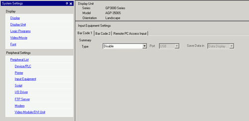
From the System Settings, click [Input Equipment] to display the following screen.
From the [Type] drop-down list, select [Two-Dimensional Code Reader].
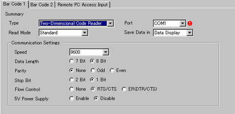
In the [Port] drop-down list, select the port to which you want to connect.
![]()
If the port is also used for other devices/PLCs, ![]() displays to the right of the [Port] as above.
displays to the right of the [Port] as above.
A two-dimensional code reader can be set in COM1, USB, and USB/SIO. When IPC Series is selected on the Display, only COM1 can be set.
Set the [Read Mode].
In [Communication Settings], set [Speed], [Data Length], [Parity], [Stop Bit], [Flow Control], and [5V Power Supply].
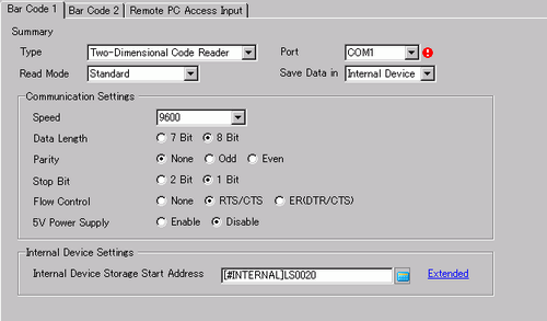
From the [Save Data In] drop-down list, select a data storage location.
From the [Internal Device Storage Start Address], set the data storage internal device's start address.
![]()
For the internal device's address setting range, refer to 16.2.1 Code Data storage area.
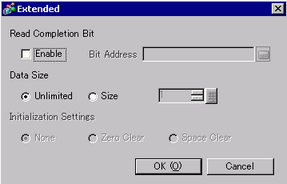
Click [Extended] to configure the [Read Completion Bit], [Data Size] and [Initialization Settings].
![]()
When [Read Completion Bit] is not set, when data is read continuously the data gets overwritten.
If [Read Completion Bit] is set, turn OFF the [Read Completion Bit] when input is complete. The display unit will not read code data without turning the read completion bit OFF.