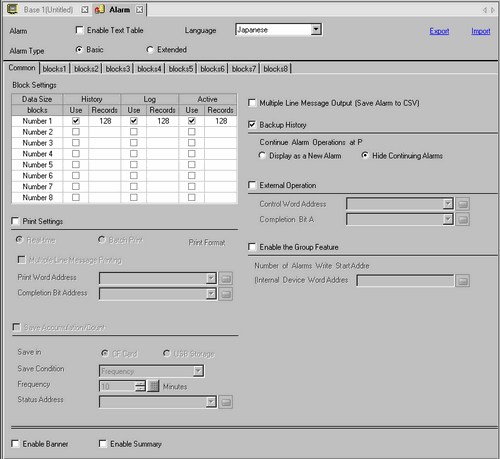
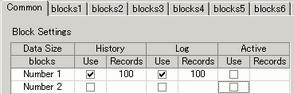
You can set the block, display mode, and the number of Alarm Histories stored for Alarm Message (History).
Set the display mode and the number of Alarm History records (the number of Alarm Histories stored in the display unit) in each mode for each block. A maximum of 768 Alarm Histories can be set.

When IPC Series is selected, the alarm data size sets the Alarm History maximum at 10000.
Block
A group of Alarm Messages to be registered. A maximum of 8 blocks can be used.
Display Mode
Choose the Alarm Message display method from [History], [Log], or [Active]. Choose [Active] to display only alarms which are currently triggered. To save old alarms choose [History] or [Log].
|
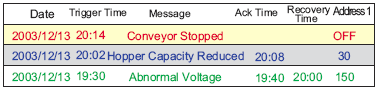
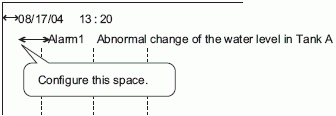
[History] |
Displays Alarm Messages, data, trigger date, and time, in the order they are triggered. The time when the Alarm is acknowledged or recovered will be added to the same row. The change in the state of each Alarm can be viewed on a single row.
|
|
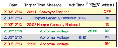
Log |
The messages, date/time, and read data are displayed in separate rows every time the state changes from [Trigger], [Acknowledged], to [Recovery]. The date can be viewed in every state.
|
|
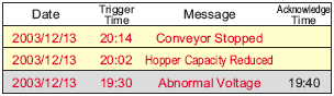
Active |
Only [Trigger] alarms are displayed. When an alarm recovers, it is automatically erased.
|
Use
Select the [Display Mode] to be used. A total of 8 display modes at maximum can be set for the whole Alarm History.
Records
Set the number of Alarm Histories stored for each display mode. Up to 768 Alarm Histories can be set in total. When triggered alarms exceed the specified number, the oldest alarm is deleted.
When IPC Series is selected, the alarm data size sets the Alarm History maximum at 10000.
Select whether or not to print the Alarm History.
 19.11.2 Restrictions for Printing Alarm History
Real-time Print/Batch Print
Choose the printing timing from [Real-time Print] or [Batch Print].
Alarm history is printed every time an alarm is [Triggered], [Acknowledged], and [Recovery].
The print format is the same as the display format of [Log].
Even when two or more blocks are used, printing is performed as occasion arises regardless of the block.
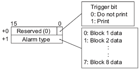
When the bit 0 in [Print Word Address] is turned ON, the whole Alarm Histories stored in the designated block are printed.
The print format is determined by the [Display Mode] settings.
The settings are checked in the order of [History], [Log], [Active], and data is printed in the format of the first [Display Mode] set [On].
For example, when printing block 1
In this case, the block is printed using [History] format. If [History] were not set, the data would be printed using [Log] format. A page feed occurs after printing.
Multiple Line Message Printing
Specify whether to display alarm messages on lines separate from other information when printing. Since the message display area expands, you can quickly verify contents of long messages. To specify the number of lines, from [Alarm Parts]-[Basic]-[Message Display Method], select [Multiple line display], then define the number of lines to display in the [Lines per Message] field.
Print Word Address
This address controls the printing of the Alarm History. After setting the type of alarm, turn ON the trigger bit (bit 0) to start printing.
Completion Bit Address
Set the bit address that will tell you when printing has completed. This bit will turn ON when printing finishes.
After the [Completion Bit] has been confirmed as ON, please turn it OFF again. It is recommended to turn OFF the bit 0 of [Print Word Address] also at this time.
Displays the [Print Format Settings] dialog box.
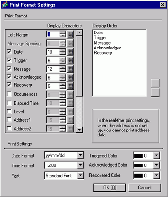
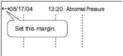
Left Margin
Select the spacing between the character of the left-most item and the border from 0 to 100 characters.
Message Spacing
You can define this when [Alarm Parts]-[Basic]-[Message Display Method]-[Multiple line display] is selected. The maximum number of characters that can display on one line is 160 characters. 160 characters minus the total [Display Characters] and [Left Margin] is the number of characters in the message that can display on one line. Set [Display Characters] from 0 to 20.
Select blocks to print
From [Date], [Trigger], [Message], [Acknowledged], [Recovery], [Occurrences], [Elapsed Time], [Level], and [Address 1] to [Address 8], specify items to print.
Date
Prints the date when the alarm was triggered.
Trigger
Prints the time when the alarm was triggered.
Message
Prints Alarm Message.
When [Alarm Parts]-[Basic]-[Message Display Method]-[Multiple line display] is selected, messages are always displayed and you cannot clear the check box.
Acknowledge
Prints the time when the alarm message was confirmed.
Recovery
Prints alarm's recovery time.
Occurrences
Prints the number of times the alarm was triggered. The maximum count is 65535.
Elapsed Time
Prints the total duration of time when the alarm was in the triggered state. The maximum duration is 9999 hours 59 minutes 59 seconds.
Level
Prints the alarm's importance level.
Address1 - Address8
Prints data that is retrieved when the alarm is triggered, acknowledged, or recovered.
Display Characters
Set the number of characters displayed for each item. Each item's setting range is as follows.
|
Date |
5 to 100 or 8 to 100 single-byte characters (The setting range differs depending on the selected date format) |
|
Trigger, Acknowledged, Recovery |
5 to 100 or 8 to 100 single-byte characters (The setting range differs depending on the selected time format) |
|
Message |
1 to 160 single-byte characters (up to 192 characters when [Alarm Type] is set to [Extended]) |
|
Occurrences, Elapsed Time, Level |
2 to 100 single-byte characters |
|
Addresses 1 to 8 |
0 to 100 single-byte characters |
When you want to provide spaces between the items, set [Total Display Digits] larger than the number of characters that will actually be displayed.
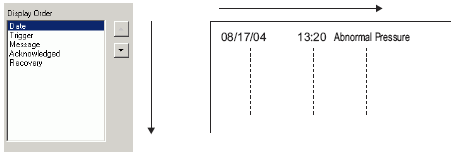
Display Order
Set the display order of all items. Blocks starting from the top of this list will be printed from left to right.
Date Format
Choose a print format for the date from [yy/mm/dd], [mm/dd/yy], [dd/mm/yy], and [mm/dd].
Time Format
Choose a print format for the time from [12:00], [24:00], [12:00:00] or [24:00:00].
Font
Choose a font type for the Alarm Message from [Standard Font] or [Stroke Font].
Triggered Color/Acknowledged Color/Recovered Color
Choose from 8 colors for the Alarm Message's [Trigger], [Acknowledged], and [Recovery] colors. Messages are printed in the specified colors regardless of the display unit type.
When white is selected, messages are printed in black.
When the [Display Mode] is [History] and [Batch Print] is set, the trigger color will be used when printing a triggered alarm, the acknowledge color for an acknowledged alarm, and the recovery color for a recovered alarm. However, when acknowledging a previously recovered alarm, the recovery color will be used for printing. The color setting is effective for text only. The background color will not be printed.
Multiple Line Message Output (Save Alarm to CSV)
Specify whether to display alarm messages on lines separate from other information when outputting to CSV. Since the message display area expands, you can quickly verify contents of long messages. Regardless of the [Alarm Parts]-[Basic]-[Line per Message] setting, messages will be displayed on a single line.
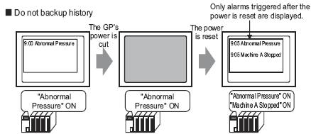
Select whether or not to backup the Alarm History to the backup SRAM of the display unit.19.12 About Backup SRAM
When backup is not selected and the display unit is turned OFF, all the Alarm Histories displayed before are erased. When the display unit is turned ON again, only the alarms triggered at the time and afterward are displayed.
GP-4100 series back up to user memory, instead of SRAM.
Alarm Continuous Action at Power ON
Select the display method to use when power is turned ON.
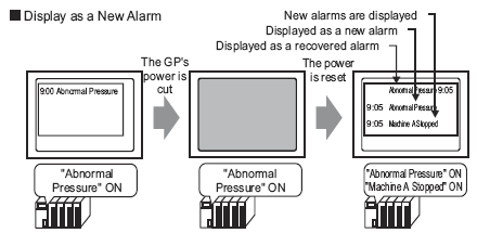
Display as a new Alarm
The information of the host (PLC) before the display unit was turned OFF is not retained. The Alarm Messages that were displayed before the GP was turned OFF are displayed as recovered state after the power is turned ON again. Any continuing alarms are separately displayed as new alarms.
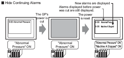
Hide Continuing Alarms
The information of the host (PLC) before the display unit was turned OFF is retained. The Alarm Messages that were displayed before the GP was turned OFF are continuously displayed when power is turned ON again. If the trigger/recovery state of alarms changes after the GP was turned ON again, the change is displayed.
Backup Function Examples
Storage Frequency
When using GP-4100 series, set up the frequency at which alarm history data is saved to user memory from 1 to 60 minutes.
When the defined frequency elapses, if there are no data changes from the previous save, the storage operation does not take place.
You can store history data up to 200,000 times.

If you turn off the display unit in the middle of saving history data, all the data may be gone or you may not be able to save data anymore. Before turning the display unit off, turn ON the #H_Control_StopAlarmSave system variable and then save history data.
Turning ON this bit before turning off the display unit enables you to save history data without the [Storage Frequency] triggering an automatic save operation.
For more information about system variables, please see the following.A.7.2.1 Bit - #H System Variables
Please save history data before going to offline mode.
If you enter offline mode before saving, reset will cause the loss of all the latest history data.1.3.6 GP-4100 Series
External Operation
Select whether or not to perform [Ack All], [Clear All], [Clear All Number of Occurrences], and [Clear All Accumulated Time] from the host (PLC).
19.11.6 Restrictions for Running External Operations from Multiple Display Units
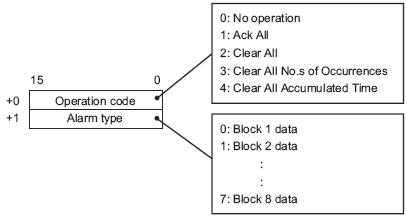
Control Word Address
Set the address which will control the type of operation performed from the PLC (operation code), and the type of alarm.
When an external operation is performed, it handles all Alarm Messages in the block (active, history, log). For example, if you perform a [Clear All] on block 1, all Alarm Messages in block 1 (active, history, log) are cleared. Within a block, Active, History, and Log cannot be operated individually.
The operation's order is [History], [Log], [Active].
Completion Bit Address
Set the address which will monitor the completion of the operation. This bit will turn ON when the operation finishes.
Select whether or not to use the Group feature. Set this feature to count the number of times that alarms have been triggered by group number.
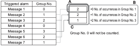
Number of Alarms Write Start Address (Internal Word Address)
(A)
Set the start address in the display unit's internal device to write the number of alarm occurrences.
(B)
Among the addresses set up in (A), only those with the registered group number are used as the area for the writing frequency of internal device addresses.
(C)
Each time an alarm occurs, data in the corresponding group number's address (internal device) will be increased by 1.
The largest group number available is 6096. Hence, you can specify a different group number for every alarm message.
Please ensure that the number of groups is within the internal device's area (USR area or LS area). For the LS area, refer to the following.A.1.4 LS Area (Direct Access Method Area)
The alarm frequency gets erased when the display unit is turned OFF. When backing up the data, please use the internal device's backup feature.5.19.3 Display Unit (Operation) Settings Guide
The alarm occurrence counts from 0 to 65535. The occurrence count cannot count past 65535.
When data is written to an internal device which stores alarm frequency or the display unit's power turns OFF, data are cleared and not counted properly.
The data format of the alarm frequency is fixed as Bin.
Alarms with group number 0 are not counted.
Save Accumulation/Count
Specify whether the accumulated time of an alarm and the number of times an alarm is triggered is saved to an external storage device.
To enable [Save Accumulation/Count], in the Alarm editor's [Block Settings] tab, select the [Records] and [Backup History] check boxes.
Save in
Select the "Save in" location from [CF card] and [USB storage].
Save Condition
Selects a condition to begin saving from [Frequency], [Bit ON], or [Bit Change].
Frequency
Set the save cycle (1 to 60 minutes).
Bit ON
Saves when the address specified in the Control Bit Address turns ON.
Bit Change
Saves when the address specified in the Control Bit Address changes (ON/OFF).
Frequency
When the [Save Condition] is set to [Frequency], set the save frequency (1 to 60 minutes).
Control Bit Address
When the [Save Condition] is set to [Bit ON] or [Bit Change], define the trigger bit address for saving.
Status Address
Specify the address where the save state will be stored.
|
Status |
Description |
|
0x0000 |
Output complete |
|
0x0001 |
Outputting |
|
0x2000 |
No data to write (for example, when there are 0 registered messages) |
|
0x3000 |
File write has failed |
|
0x4000 |
CF Card/USB storage device missing (has not been inserted, or the CF card cover is not closed) |
|
0x5000 |
CF Card/USB storage device Read Error (read has failed) |
|
0x6000 |
CF Card/USB storage device Write Error (write has failed, no free space) |
|
0x7000 |
CF Card/USB storage error (storage error) |
|
0x8000 |
File read has failed (formatting error, inconsistency with the alarm settings of the main unit) |
When the file is not saved, the number of occurrences and the accumulated time become 0, and 0x8000 is stored as the status.
Configure Alarm Messages to display as scroll banners.
19.10.1.4 Alarm Settings (Banner)
This setting displays currently active alarms in a list.