A.7.2.1 Bit - #H System Variables
|
Variable Name |
Description |
READ |
WRITE |
|---|
|
#H_Alarm_Trigger |
The alarm is triggered (regardless of the particulars that occurred) |
○ |
○ |
|
#H_Control_Buzzer |
Buzzer Output |
○ |
○ |
|
#H_Control_BuzzerEnable |
Enable the Buzzer Output |
○ |
○ |
|
#H_Control_HardcopyPrint |
Print Control for Screen Hard Copy |
○ |
○ |
|
#H_Control_JpegCaptureEnable |
Enable Screen Capture |
○ |
○ |
|
#H_Control_JpegCaptureTrigger |
Control of Screen Capture |
○ |
○ |
|
#H_Control_PLCmonopoly |
PLC monopoly during Serial Multilink connection |
○ |
○ |
|
#H_Control_PrintCancel |
Control of Print Cancel |
○ |
○ |
|
#H_Control_USBDetachTrigger |
USB Removal Control*1 |
○ |
○ |
|
#H_Control_SecureWriteTrigger |
Starts writing security data*2 |
○ |
○ |
|
#H_Control_SecureWriteMode |
Security Data Write Mode |
○ |
○ |
|
#H_Control_SecureDeleteMode |
Security Data Delete Mode |
○ |
○ |
|
#H_Control_SecureReadDevice |
Location where security data is read from |
○ |
○ |
|
#H_Control_StopAlarmSave |
Request to stop alarm save operation |
○ |
○ |
|
#H_DeviceMonitor |
Device Monitor Start |
○ |
○ |
|
[PLC*]#H_ErrorStatus*5 |
Communication error status of PLC (Device*) |
○ |
× |
|
#H_Expression_BCD_Err*3 |
BCD error during animation operation |
○ |
○ |
|
#H_Expression_Division_Err*3 |
Zero operation error during animation operation |
○ |
○ |
|
#H_Expression_Overflow |
Turns ON when animation stores a signed 64-bit value as a signed 32-bit value. |
○ |
○ |
|
#H_IsLockedState |
Operation locked |
○ |
× |
|
#H_IsLockOwner |
Operation Lock resides in the operating Server/Viewer or Master/Slave |
○ |
× |
|
#H_IsAutoUnlockTimerMoved |
Operational check of Auto Unlock Timer. |
○ |
× |
|
#H_LadderMonitor |
Start Ladder Monitor*4 (No cache trigger) |
○ |
○ |
|
#H_LadderMonitorCache |
Start Ladder Monitor *4 (Cache trigger) |
○ |
○ |
|
#H_IsMasterDispUnit |
Master station of Ethernet Multilink |
○ |
× |
|
#H_IsSlaveDispUnit |
Slave station of Ethernet Multilink |
○ |
× |
|
#H_Reset |
Resets the unit. |
× |
○ |
|
#H_Status_AlarmSave |
Alarm save status |
○ |
× |
|
#H_Status_DispOnOff |
Display ON/OFF |
○ |
× |
|
#H_Status_JpegCaptureCompletion |
Screen Capture Status (Completed) |
○ |
× |
|
#H_Status_JpegCaptureProcess |
Screen Capture Status (Processing in Progress) |
○ |
× |
|
#H_Status_PLCmonopoly |
Another Display has a PLC monopoly during a Serial Multilink connection |
○ |
× |
|
#H_Status_Print |
Printer Status |
○ |
× |
|
#H_Status_SecureWriteProcess |
Writing security data |
○ |
× |
|
#H_Status_SecureWriteCompletion |
Writing security data completed |
○ |
× |
|
#H_Status_USBUsing |
Status while USB is in use*1 |
○ |
× |
|
[PLC*]#H_ScanOffStatus*5 |
Scanning status of PLC (Device*) |
○ |
× |
|
[PLC*]#H_ScanOffControl*5 |
PLC (Device*) scan control |
○ |
○ |
#H_Alarm_Trigger
This is a system variable that turns ON when an alarm is triggered, regardless of the Alarm type.
Due to the alarm being triggered, it can be used as an alarm trigger when performing processes such as screen change or data capture.
This system variable can be arbitrarily turned ON/OFF.
Once this system variable is turned ON, as long as it is not arbitrarily turned OFF, it remains ON until the display unit is turned OFF.
#H_Control_Buzzer
This is a system variable that controls display unit buzzers.
Stored in L001401 when the communication method is Direct Access or to 001101 when the method is the Memory Link Method. This system variable turns ON during a buzzer output.
#H_Control_BuzzerEnable
This is a system variable that controls the display unit buzzer function.
Stored in L001404 when the communication method is Direct Access or to 001104 when the method is the Memory Link Method. When this system variable is ON, buzzer output is enabled.
#H_Control_HardcopyPrint
This is a system variable used to print the display unit screen. When the bit of this system variable is turned ON, the screen on the display unit begins printing. Stored in L001402 when the communication method is Direct Access or to 001102 when the method is the Memory Link Method.
#H_Control_JpegCaptureEnable
This is a system variable that controls the saving of display unit screens by Pro-Server EX. Stored in LS207600. When the bit of this system variable is turned ON, display unit screens can be saved using Pro-Server EX.
#H_Control_JpegCaptureTrigger
This is a system variable that saves screens being displayed on the display unit. Stored in LS207200. When the bit of this system variable is turned ON, the display unit screen can be saved in Jpeg format on a CF card attached to the display unit.
#H_Control_PLCmonopoly
Turns ON when there is a PLC monopoly during a Serial Multilink connection. Stored in Bit 7 of LS0014.
#H_Control_PrintCancel
This system variable cancels printing operations of the printer connected to the display unit. When the bit of this system variable is turned ON, all printing processes set for display unit are canceled.
Stored in L001411 when the communication method is Direct Access or to 001111 when the method is the Memory Link Method.
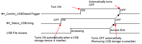
#H_Control_USBDetachTrigger
This is a system variable that is used when removing a USB storage device from the display unit. When this system variable is turned ON, #H_Status_USBUsing is turned OFF and the USB storage device can be removed from the display unit.
#H_Control_SecureWriteTrigger
This is a system variable used when starting a writing operation of security data.
For writing security data, refer to the following.
 #H_SecurityWriteControl
#H_Control_SecureWriteMode
This is a system variable used for selecting the write mode for security data.
For writing security data, refer to the following.
#H_SecurityWriteControl
#H_Control_SecureDeleteMode
This is a system variable that selects the delete mode for security data.
For writing security data, refer to the following.
#H_SecurityWriteControl
#H_Control_SecureReadDevice
This is a system variable used for selecting the read destination for security data.
For writing security data, refer to the following.
#H_SecurityWriteControl
#H_Control_StopAlarmSave
System variable for saving alarm history.
With GP-4100 series, if you turn off the display unit in the middle of saving history data, all the data may be gone or you may not be able to save data anymore.
Turning ON this bit before turning off the display unit enables you to save history data without the [Storage Frequency] (available from the [Common Settings] menu's [Alarm] command) triggering an automatic save operation.
When save is complete, #H_Status_AlarmSave turns ON.
#H_DeviceMonitor
This is a system variable that displays the status of a device monitor. When the bit of this system variable is turned ON, the device monitor will start up.
[PLC*]#H_ErrorStatus
This is a system variable that displays the state of a communication error in the device/PLC.
The communication status is normal.
There is an error in the communication status.
#H_Expression_BCD_Err
When operating animations, turns ON when a "BCD error" occurs.
#H_Expression_Division_Err
When operating animations, turns ON when a "Zero division error" occurs.
#H_Expression_Overflow
When operating animations, performs "Curving" when storing data "with 64-bit signs" as "with 32-bit signs". This system variable turns ON when that Curving occurs.
#H_IsLockedState
This is a system variable that displays the Operation Lock status of the display unit or GP-Viewer EX. If the display unit or GP-Viewer EX undergoes Operation Lock due to a different display unit or instance of GP-Viewer EX, the bit of this system variable turns ON.
#H_IsLockOwner
This is a system variable that displays the Operation Lock status of the display unit or GP-Viewer EX. If the display unit or GP-Viewer EX undergoes Operation Lock due to a different display unit or instance of GP-Viewer EX, the bit of this system variable turns ON.
#H_IsAutoUnlockTimerMoved
This is a system variable that displays the operation state of the Auto Unlock Timer for Operation Lock.
Not operating.
Operating.
#H_LadderMonitor
This is a system variable that starts the Ladder Monitor. Stored in LS207801. When the bit of this system variable is turned ON, the Ladder Monitor will start up.
#H_LadderMonitorCache
This is a system variable that starts the Ladder Monitor. Stored in LS207803. When the bit of this system variable is turned ON, the Ladder Monitor starts up and the ladder programs in the CF cache are displayed.
#H_IsMasterDispUnit
This is a system variable that displays the station status of the display unit during an Ethernet Multilink connection. Turns ON for the Master station of Ethernet Multilink.
#H_IsSlaveDispUnit
This is a system variable that displays the station status of the display unit during an Ethernet Multilink connection. Turns ON for the Slave station of Ethernet Multilink.
#H_Reset
This is a system variable that restarts the display unit. When the bit of this system variable is turned ON, the display unit restarts.
#H_Status_AlarmSave
When using GP-4100 series and #H_Control_StopAlarmSave is ON and alarm history save operation is completed, this system variable turns ON. Resetting #H_Control_StopAlarmSave OFF turns this system variable OFF.
#H_Status_DispOnOff
This is a system variable that displays the screen display state of the display unit.
Stored in L000609 when the communication method is Direct Access or to 000109 when the method is the Memory Link Method. This system variable turns ON during a display unit screen display.
#H_Status_JpegCaptureCompletion
This is a system variable that displays the save status of the screen being displayed on the display unit. This system variable turns ON after a GP screen is saved.
#H_Status_JpegCaptureProcess
This is a system variable that displays the save status of the screen being displayed on the display unit. This system variable turns ON while a GP screen is being saved.
#H_Status_PLCmonopoly
Turns ON when another Display has a PLC monopoly during a Serial Multilink connection. Stored in Bit 7 of LS0006.
#H_Status_Print
This is a system variable that displays the print status of the display unit. This system variable turns ON during a printing operation for the following function. Stored in L000602 when the communication method is Direct Access or to 000102 when the method is the Memory Link Method.
Screen Hard Copy
Banner Alarm
Alarm History (Real-time, Batch Print)
Sampling (Real-time, Batch Print)
CSV display function (Partial Printing, Print All)
#H_Status_SecureWriteProcess
This is a system variable that displays the write status for security data. This system variable turns ON when security data is being written.
#H_Status_SecureWriteCompletion
This is a system variable that displays the write status for security data. This system variable turns ON when after security data has been written.
#H_Status_USBUsing
This is a system variable that displays the connection status of a USB storage device connected to the display unit.
The bit state of this system variable is as follows.
One of the following states.
The USB storage device is connected to the display unit.

Even if the USB storage device is physically connected to the display unit, if this system variable is turned OFF, access to the USB storage device is disabled. Remove the USB storage device and insert again.
Do not perform any of the following actions while writing data to the USB storage device. This may result in an incomplete file or damage to the USB storage device.
Going to offline mode
Transfering screen data to the Display Unit
Removel and insertion of the USB storage device
[PLC*]#H_ScanOffStatus
This is a system variable that displays the communication scan state of the device/PLC. This system variable turns ON during a communication scan of the device/PLC..
[PLC*]#H_ScanOffStatus
This is a system variable that controls the communication scan of the device/PLC. Values for the device/PLC Nodes 1 to 32 are stored in order in LS955000 to LS955115. The same applies for the following, with the values of the second PLC stored in LS955200 to LS955135, the values of the third PLC stored in LS955400 to LS955515, and the values of the fourth PLC stored in LS955600 to 955715.
When the bit of this system variable is turned ON, the device/PLC communication is scanned.