
Installation Requirements
This product is designed for use on flat surfaces of UL 50/50E, Type 1, Type 4X (indoor use only), Type 12 or Type 13 enclosure.
Mount this product in an enclosure that provides a clean, dry, robust and controlled environment (IP65F, IP66F, IP67F, UL 50/50E, Type 1, Type 4X [indoor use only], Type 12 or Type 13 enclosure).
For 10-inch Wide, 12-inch Wide, 15-inch Wide, 19-inch Wide and 22-inch Wide models, the front surface is rated for IP66F, IP67F, UL 50/50E, Type 1, Type 4X (indoor use only), Type 12 and Type 13 enclosure.
For 12-inch and 15-inch models, when using a factory-installed front USB cover (without screw), the front surface is rated for IP65F, IP67F, UL 50/50E and Type 1 enclosures. When using a front USB cover (with screw) (PFXZCDCVUS1), the front surface is rated for IP66F, IP67F, UL 50/50E, Type 1, Type 4X (indoor use only), Type 12 and Type 13 enclosure.
| Display front surface | Enclosure front surface | ||
|---|---|---|---|
| 12-inch and 15-inch | 10-inch Wide/12-inch Wide/15-inch Wide/19-inch Wide/22-inch Wide | ||
| Without screw | With screw | ||
| IP65F, IP67F, UL 50/50E, Type 1 | IP66F, IP67F, UL 50/50E, Type 1, Type 4X (indoor use only), Type 12, Type 13 | IP66F, IP67F, UL 50/50E, Type 1, Type 4X (indoor use only), Type 12, Type 13 | IP65F, IP66F, IP67F, UL 50/50E, Type 1, Type 4X (indoor use only), Type 12, Type 13 |
For 12-inch and 15-inch models, regardless of using a factory-installed front USB cover or a front USB cover with screw, when the front USB cover is open, the front surface is rated for UL 50/50E and Type 1 enclosure.
Be aware of the following when building this product into an end-use product:
-
The rear face of this product is not approved as an enclosure. When building this product into an end-use product, be sure to use an enclosure that satisfies standards as the end-use product’s overall enclosure.
-
Install this product in an enclosure with mechanical rigidity.
-
This product is not designed for outdoor use. UL certification obtained is for indoor use only.
-
Install and operate this product with its front panel facing outward.
 CAUTION CAUTION |
|---|
|
RISK OF BURNING INJURY
Failure to follow these instructions can result in injury or equipment damage.
|
-
Box Module:
Depending on the panel’s material and design, the panel’s installation surface may need to be strengthened. If high levels of vibration are expected and this product’s installation surface can move (such as because of a panel door opening or closing), due consideration should be given to this product’s weight.Panel Type:
Check that the installation wall or cabinet surface is flat, in good condition and has no jagged edges. Metal reinforcing strips may be attached to the inside of the wall, near the panel-cut, to increase its rigidity. -
Box Module:
Determine the thickness of the panel in consideration of its material and strength as well as the environment in which this product is used. The thickness must be 1.6 mm (0.06 in) or more, considering the length of M4 screws.Panel Type:
Decide on the thickness of the enclosure wall, based on the level of strength required. Even if the installation wall thickness is within the recommended range for the Panel Cut Dimensions, depending on wall’s material, size, and installation location of this product and other devices, the installation wall could warp. To prevent warping, the installation surface may need to be strengthened. -
Check that the ambient air temperature and the ambient humidity are within their specified ranges in Environmental Specifications. When installing this product in a cabinet or enclosure, the ambient air temperature is the cabinet’s or enclosure’s internal and external temperature.
-
Internal temperature
-
External temperature
-
-
Be sure that heat from surrounding equipment does not cause this product to exceed its standard operating temperature.
-
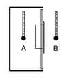
When mounting Panel Type in portrait orientation, ensure that the right side of this product faces up. In other words, the power connector should be at the top. For the Box Module, see Box Module Installation.
NOTE: Please make sure your applications support portrait orientation of the display.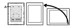
-
Power connector
-
-
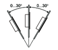
When installing this product in a slanted position, the product face should not incline more than 30°.
-
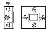
For easier maintenance, operation and improved ventilation, install this product at least 100 mm (3.94 in) away from adjacent structures and other equipment as shown in the following illustration:
Pressure Differences
When applying and installing this product, it is important that steps are taken to eliminate any pressure difference between the inside and the outside of the enclosure in which this product is mounted. Higher pressure inside the enclosure can cause delamination of the front membrane of the display. Even a small pressure difference inside the enclosure will act on the large area of the membrane and can result in sufficient force to delaminate the membrane and thus cause failure of the touch capability. Pressure differences can often occur in applications where there are multiple fans and ventilators moving air at different rates in different rooms. Please follow these techniques to ensure that this product's function is not impacted by this mis-application:-
Seal all conduit connections inside of the enclosure, especially those that lead to other rooms that may be at a different pressure.
-
Where applicable, install a small weep hole at the bottom of the enclosure to allow equalization of the internal and external pressure.