ODVA DeviceNet Slave
|
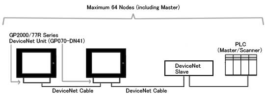
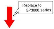
When replacing PLC, which is used in GP2000/ 77R/ 70 series, into GP3000 series.
|
|
| |
|
Reminder in replacing GP2000/77R/70 series into GP3000 series *Make sure to read it.
|
| ● Communication Settings |
| - |
The baudrate settings are different between GP-PRO/PB3 and GP‐Pro EX. |
|
|
| GP-PRO/PB3: |
The back dip switch of the DeviceNet expansion unit is used to setup the baud rate and the node number. |
| GP-Pro EX: |
The node number and the baud rate are set in "Communication Settings". |
|
| ● Address Formats |
| - |
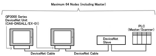
With GP-PRO/PB3, Input Area and Output Area of the master are allocated to LS Area.
With GP-Pro EX, there are dedicated devices for "input" and "output". However, LS Area allocated into Input Area and Output Area will not be converted to "input" and "output" devices. Therefore, please use the Address Block Conversion utility to convert addresses.
|
|
-
|
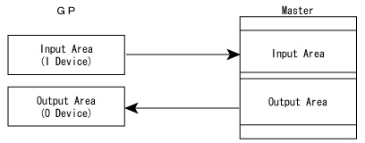
Definitions of Input Area and Output Area are different between GP-PRO/PB3 and GP-Pro EX as below.
|
|
| With GP PRO/PB3, Input Area of the master is described as Output Area of GP, and Output Area of the master is described as Input Area of GP. |
|
|
| The description with GP-Pro EX is matched to the master. |
|
|
By this change, Input Area Size is converted to Output Area Size, and Output Area Size is converted to Input Area Size after conversion.
|
| ・Setting Input Area Size/Output Area Size before Conversion (GP-PRO/PB3) |
|
|
| ・Setting Input Area Size/Output Area Size after Conversion (GP-PRO/PB3) |
|
|
|
| NOTE |
|
・
|
Procedure for Address Block Conversion after Conversion |
|
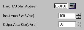
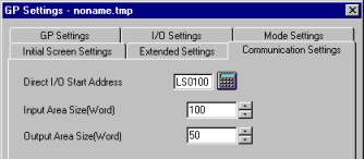
Confirm [Direct I/O Start Address], [Input Area Size], and [Output Area Size] in GP Settings.
|
|
| e.g. |
[Direct I/O Start Address] LS0100
[Input Area Size] 100
[Output Area Size] 50 |
|
|
|
1.
|
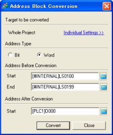
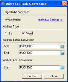
Open the converted project file of GP-Pro EX. On the [Project] menu, select [Utility] - [Convert Addresses] and open the [Address Block Conversion] window.
|
|
|
|
2.
|
Convert the word addresses.
|
|
|
|
| Address Before Conversion |
|
| Start: |
The address set to Direct I/O Start Address with GP-PRO/PB3 (e.g.;[#INTERNAL]LS100) |
| End: |
Start + Input Area Size - 1 (e.g.; [#INTERNAL]LS199) |
|
| Address After Conversion |
|
|
|
|
|
| Address Before Conversion |
|
| Start: |
The address set to Direct I/O Start Address with GP-PRO/PB3 + Input Area Size (e.g.; [#INTERNAL]LS200) |
| End: |
Start + Output Area Size - 1 (e.g.; [#INTERNAL]LS249) |
|
| Address After Conversion |
|
|
|
|
3.
|
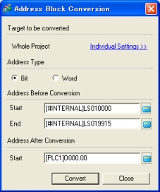
Convert the bit addresses.
|
|
|
|
| Address Before Conversion |
|
| Start: |
Bit 0 of the address set to Direct I/O Start Address with GP-PRO/PB3 (e.g.; [#INTERNAL]LS10000) |
| End: |
Bit 15 of "Start + Input Area Size - 1" (e.g.; [#INTERNAL]LS19915) |
|
| Address After Conversion |
|
|
|
|
| Address Before Conversion |
|
| Start: |
Bit 0 of "the address set to Direct I/O Start Address with GP-PRO/PB3 + Input Area Size" (e.g.; [#INTERNAL]LS20000) |
| End: |
Bit 0 of " Start + Output Area Size - 1" (e.g.; [#INTERNAL]LS24915) |
|
| Address After Conversion |
|
|
|
|
Address Block Conversion is completed. |
|
|
|
|
|
|
|
|
|
| Warning message of [Project converter] |
| - |
When the project file of GP-PRO/PB3 will be converted by [Project converter], these messages will show in following cases. |
|
|
Warning Message
|
Description
|
|
Slave Input/Output ["LS" Devices] are not converted. Please use [Project] [Utility] [Convert Address] to convert them to I/O. The details please refer to our support site (http://www.pro-face.com/otasuke/).
|
With GP-PRO/PB3, Input Area and Output Area of the master are allocated to LS Area.
With GP-Pro EX, there are dedicated devices for "input" and "output". However, LS Area allocated into Input Area and Output Area will not be converted to "input" and "output" devices. Therefore, please use the Address Block Conversion utility to convert addresses.
|
*
|
Please refer to "Address Formats" above for more details. |
|
|
|
|
| Please refer |
 |
|
 |
|