![]()
-
For details on how to draw parts, and defining the address, shape, color, and labels, please see the parts editing topic.
 8.7.1 Editing Parts
![]()
For details on how to draw parts, and defining the address, shape, color, and labels, please see the parts editing topic.
![]() 8.7.1 Editing Parts
8.7.1 Editing Parts
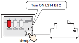
Create a switch to operate the internal device LS14 bit 2.
Configure connection settings for the printer.
![]() 35.3.3 Procedure - Connecting a Printer Directly to the Display Unit
35.3.3 Procedure - Connecting a Printer Directly to the Display Unit
From the [Parts (P)] menu, select [Switch Lamp (C)], point to [Bit Switch (B)], and draw the Switch Part on the screen. Alternatively, you can click ![]() and then draw the Switch Part.
and then draw the Switch Part.
Double-click the placed Switch part. The following dialog box appears.
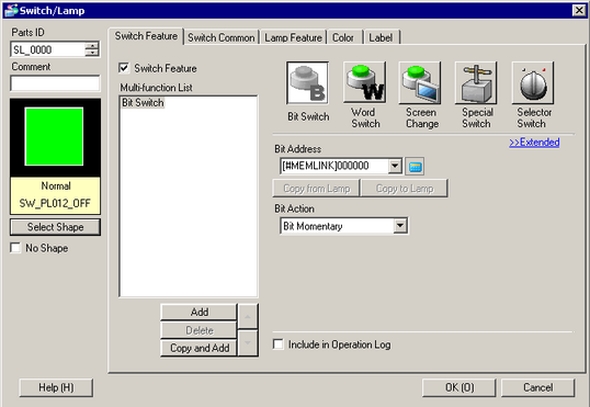
In [Select Shape], select the Switch shape.
Designate the display unit's internal device LS14 Bit 2 (print start bit) in [Bit Address].
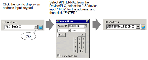
![]()
Alternatively, select the variable #H_Control_HardcopyPrint from the [Bit Address] pull-down menu to create the same operation switch.
From [Bit Action], choose [Bit Invert].
![]()
As needed, set the color and display text on the [Color] and [Label] tabs, and click [OK].
A switch used to start screen print out has been created.
![]()
While printing the displayed screen, the display unit's internal device LS6 (status address) Bit 2 (printing bit) is ON. After printing, this bit automatically turns OFF. Confirm this bit OFF and then turn OFF LS14 Bit 2(print start bit).