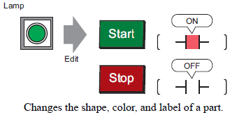
From the [Parts (P)] menu, point to [Switch Lamp (C)] and select [Lamp (L)] or click ![]() .
.
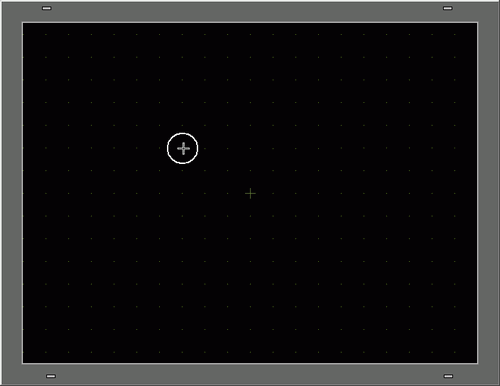
Move the pointer ![]() to the drawing board and the pointer changes to a cross-hair cursor
to the drawing board and the pointer changes to a cross-hair cursor ![]() .
.
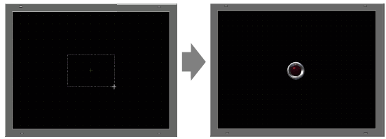
Drag the switch to the desired location. Release to place the switch.
![]()
You can also drag and drop a part from the Parts Toolbox.
From the [View (V)] menu, point to [Work Space (W)] and then click [Parts Toolbox (T)]. In the Parts Toolbox, select the [Parts Palette] and [Type] to browse various parts and shapes.
![]() 3.8.3.8 Parts Toolbox
3.8.3.8 Parts Toolbox
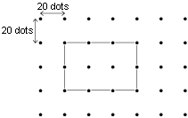
On display units that use matrix touch panel technology, set the touch area where touch-enabled parts (switches, data display units, key parts, etc.) are placed, to 20x20 pixels or greater. Then, place the parts on the screen to align with the grid.
![]() 8.2.3 Setting up Grids
8.2.3 Setting up Grids
Draw parts so they do not overlap touch areas with other parts. To display the touch area of a part, from the [View] menu click [Preferences]. In the Preferences dialog box, click [Screen Edit Style] to open its settings. Click [Display] tab and select [Show Touch Areas].
Double-click the placed lamp. The Switch/Lamp dialog box appears.
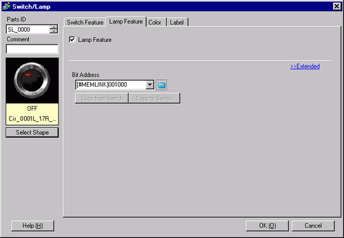
Click the icon ![]() to display the [Input Address] dialog box.
to display the [Input Address] dialog box.
Click the icon ![]() and select the [Device/PLC] and [Device]. Input the address from the keypad.
and select the [Device/PLC] and [Device]. Input the address from the keypad.
![]()
Input the address with the keypad on the Input Address dialog box. If you input the address directly from a PC keyboard, the input may not be recognized as an address.
Select the [Use as Default Value] check box and click [Ent], to register the value as the default value, so the next time it will automatically appear in the [Address Input] dialog box.
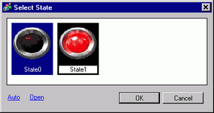
Click [Select Shape].
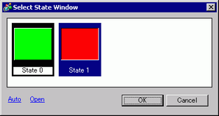
The [Select State] dialog box appears. Select [State 0] and click [Open].
Select "SW_3D202_OFF" from [Parts Picture ID].
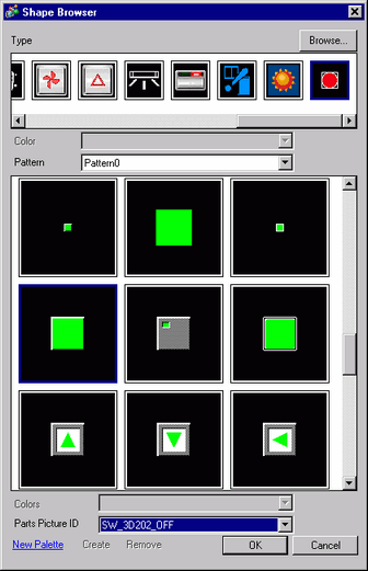
![]()
By changing [Type], you can select from multiple types of images. There are parts with 65536, 256 or 64 colors. Please select the part palette that matches the colors supported by your model.
Click [OK] and the display returns to the [Select State] window. Select [State 1] and click [Open].
Select "SW_3D202_ON" from [Parts Picture ID].
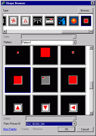
The pictures at [State 0] (OFF) and [State 1] (ON) are displayed. Click [OK].
![]()
Click [Auto] after defining the picture in [State 0] to automatically match the pictures for all other states with [State 0].
If different states have different shapes, part of a previous shape may remain in the background when touching a switch to change its state. This results because part shapes are drawn by overwriting the other.
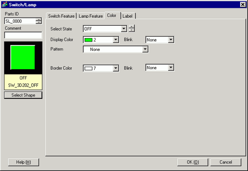
Click the [Color] tab. Confirm that [Select State] is OFF and set the color of the switch in its OFF state. For the [Display Color], click ![]() and select a color from the color palette.
and select a color from the color palette.
![]()
You cannot edit the color of Switch/Lamp menu image parts.
To change the palette to color code order, click the color code button under the palette.
Depending on the shape, you may not be able to change the color, or you may be limited to choosing from 6 colors.
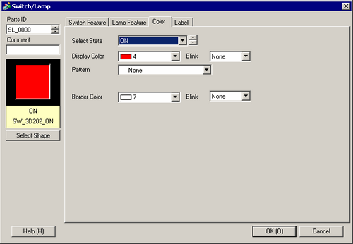
Click ![]() in [Select State] to select ON, and set the color of the switch for the ON state.
in [Select State] to select ON, and set the color of the switch for the ON state.
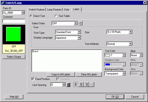
Select the [Label] tab. Click ![]() in [Select State] to select OFF, and input the text to display on the switch in the OFF state.
in [Select State] to select OFF, and input the text to display on the switch in the OFF state.
![]()
Select the switch and press [F2] key, and you can directly edit the text on the label.
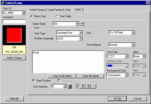
Click ![]() in [Select State] to select ON, and input the text to display on the switch in the ON state.
in [Select State] to select ON, and input the text to display on the switch in the ON state.
Click [OK] when all the settings are complete.