![]()
-
For details about the setting screen, refer to the setting guide.
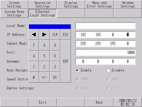
 M.17.2.7 Main Unit - Ethernet settings
 -
When using the following models, you can set up the IP address in the Transfer Tool.
-
SP5000 Series (excluding Open Box)
-
GP4000 Series models (excluding GP-410*) with a LAN port
-
LT4000 Series
-
ET6000 Series
-
ST6000 Series
-
STM6000 series
-
STC6000 Series
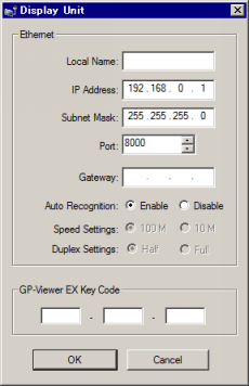
Using the Transfer Tool to set up IP address