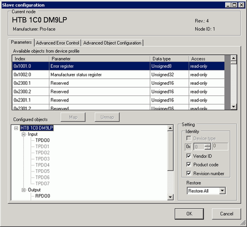
Configure detailed settings of the slave selected in the [Slave Configuration] dialog box.
Parameters
Available objects from device profile
Display the list of objects that can be mapped to PDO.
Index
Display index and sub index of the object. The sub index appears after the dot. For example, for "0x1003.2", "0x1003" is index and "2" is sub index.
Parameter
Display parameter name of the object.
Data Type
Display data type of the object. The following data types are included.
Boolean (Single bit value)
Integer8 (8 bit signed integer)
Integer16 (16 bit signed integer)
Integer24 (24 bit signed integer)
Integer32 (32 bit signed integer)
Integer40 (40 bit signed integer)
Integer48 (48 bit signed integer)
Integer56 (56 bit signed integer)
Integer64 (64 bit signed integer)
Unsigned8 (8 bit unsigned integer)
Unsigned16 (16 bit unsigned integer)
Unsigned24 (24 bit unsigned integer)
Unsigned32 (32 bit unsigned integer)
Unsigned40 (40 bit unsigned integer)
Unsigned48 (48 bit unsigned integer)
Unsigned56 (56 bit unsigned integer)
Unsigned64 (64 bit unsigned integer)
Float (32 bit single-precision floating point)
Float64 (64 bit single-precision floating point)
Visible String (ASCII text string)
Octet string (Array of 8 bit unsigned integer)
Unicode string (Array of 16 bit unsigned integer)
Bit string (Array of single bit)
Time of day (48 bit value indicating time and date)
Time difference (48 bit value indicating time)
Domain (Application specific data block)
Reserved (Reserved type)
Access
Displays access method of the objects. The following types are included.
readonly (Read only)
writeonly (Write only)
readwrite (Read/Write)
constant (Constant)
Map
Map the object selected in [Available objects from device profile] to [Configured objects] tree.
Unmap
Remove the object mapped to [Configured objects] tree.
Configured objects
Mapped objects per slave displays in tree configuration. Map the object.
TPDO
PDO sent from slave to master. When data is input from the external I/O that's connected to the selected slave, map the object here.
RPDO
PDO sent from master to slave. When data is output from the external I/O that's connected to the selected slave, map the object here.
Settings
Configure detailed settings of the item selected in [Configured objects].
Setting contents vary from when: the slave is selected on the tree, TPDO or RPDO is selected, or the mapped object is selected.
Identify
Defines whether or not to run the device type reference. Select this option to check if the structure matches the set up value in object 1000h. If 1000h is zero, reference does not take place.
Vendor ID
Displays the slave vendor ID.
Product Code
Displays the product code of the slave.
Revision Number
Displays the revision number of the device (slave) stated in the EDS file.
Restore
Return the parameters to the initial value when restarting the network. You can set so as to restore the parameters for each slave.
None
Parameters are not restored.
All
All parameters are restored.
Communication only
Restores the parameters in [Commutation Area] (1000h to 1FFFh) of [Slave Configuration/Extended].
Application only
Restores parameters in [Manufacturer Area] and [Profile Area] (6000h to 9FFFh) of [Slave Configuration/Extended].
![]()
Selected items that are not supported by the slave are not displayed. The EDS file of each slave defines whether the slave supports the selected item.
If HTB is used, the application data is not recovered even if [Application Only] is selected.
Manufacturer-defined selected items (object 0x1011 sub index 4 or later) are displayed as "extension 4" or "extension 5".
When TPDO/RPDO Is Selected
Set PDO enabled/disabled and set [Transmission Type], [Inhibit Time] and [Event Timer].

![]()
If the PDO is disabled, when you re-open the project, all the information set in the PDO is initialized to its initial values.
Since this initialization setting depends on the default setup on the slave, objects may be being mapped.
Enable
Select the check box to enable PDO.
Transmission Type
Display the transmission type for PDO in [Change Settings].
Inhibit Time
Display time when continuously transmitting PDO is inhibited only for TPDO.
Set in [Change Settings]. The time can be configured in 100 ms increments.
Event Timer
Displays transmission interval in which PDO is continuously sent. Set in [Change Settings]. The unit is in milliseconds.
Number of objects
Changes the object count for semi-static objects mapped to PDO.
![]()
It displays only if PDO for Semi-Static objects is selected.
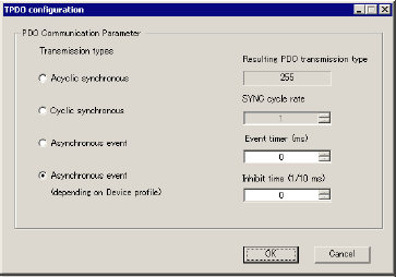
Settings
Click to display the following screen. Different screens are displayed for RPDO and TPDO.
When RPDO is selected
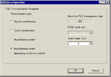
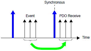
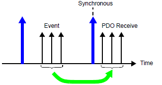
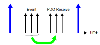
Acyclic synchronous (non cyclic)
PDO is received when an event occurs, such as when 255/254 is set, but occurs only after the next SYNC signal enters the network. In addition, if no event occurs, PDO is not received even when the SYNC signal has flown to the network.
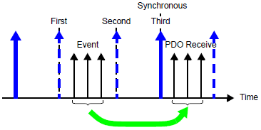
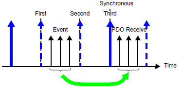
Cyclic synchronous (cyclic)
In synchronization with the SYNC signal entering the network, PDO is received based on the value set to the SYNC cyclic number.
For example, when 1 is set, PDO is received for every SYNC object. When 3 is set, PDO is received each time three SYNC signals enter the network.
The following figure shows the case in which 3 is set.
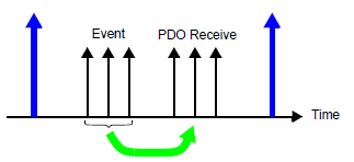
Asynchronous event (standard event)/Determined by (standard event) device profile
PDO is received immediately when an event occurred regardless of the SYNC signal. For 254, this is defined by the manufacturer. For 255, this is defined in the device profile.
The information of PDO that has been set is as follows.
|
Object number |
Sub index |
ItemName |
|---|---|---|
|
0x1400 + PDO number |
0 |
Number of RPDO |
|
1 |
COB ID |
|
|
2 |
Transmission Type |
|
|
3 |
Inhibit Time |
|
|
5 |
Event Timer |
Event Timer
When set to 255/254, sets up the interval at which events are generated for the master to transmit a PDO.
When TPDO is selected
Acyclic synchronous (non cyclic)
PDO is sent when an event occurs, such as when 255/254 is set, but occurs only after the next SYNC signal enters the network. In addition, if no event occurs, PDO is not sent even when the SYNC signal has flown to the network.
Cyclic synchronous (cyclic)
In synchronization with the SYNC signal entering the network, PDO is sent based on the value set to the SYNC cyclic number.
For example, when 1 is set, PDO is sent for every SYNC object. When 3 is set, PDO is sent each time three SYNC signals enter the network.
The following figure shows the case in which 3 is set.
Asynchronous event (standard event)/Determined by (standard event) device profile
PDO is sent immediately when an event occurred regardless of the SYNC signal. For 254, this is defined by the manufacturer. For 255, this is defined in the device profile.
Event Timer
When set to 255/254, sets up the interval at which events are generated for transmitting a PDO.
Inhibit Time
When set to 255/254, define the time when not to transmit a PDO.
When the object is selected
The set up PDO information is shown in the following object.
|
Object number |
Sub index |
Item Name |
|---|---|---|
|
0x1800 + PDO number |
0 |
Number of TPDO |
|
1 |
COB ID |
|
|
2 |
Transmission Type |
|
|
3 |
Inhibit Time |
|
|
5 |
Event Timer |
Configure how to work with the mapped object. Display on I/O Screen varies depending on the type set here.
![]() 31.9.3 Mapping I/O - CANopen
31.9.3 Mapping I/O - CANopen
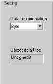
Type
Select from "Bit", "Byte", "Word" and "Dword" (Double Word).
Data Type
Data type of the selected object displays.
Advanced Error Control (when Use Heartbeat is selected)
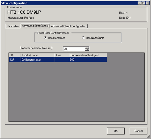
Producer Heartbeat Time
Set the transmission cycle of heartbeat. Unit is in milliseconds. The value can be from 50 to 21844. It is stored in the object 1017h on slave side.
ID
Displays Node ID of CANopen master.
Product Name
Displays the product name of CANopen master.
Alias
Displays alias of CANopen master.
Consumer Heartbeat
Consumer heartbeat of CANopen master displays. Stored in the object 1016h on master side.
Advanced Error Control (when Use Nodeguard is selected)
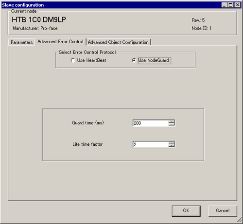
Guard Time
When NMT master polls the slaves, sets up the frequency for when slaves receive polling requests. Unit is in milliseconds. The set up range is 0, or 50 to 32767. Heartbeat is used when set to zero. It is stored in object 100Ch.
Lifetime factor
Set the time to monitor errors when NMT master polls the slaves.
An error occurs if it is not polled when the time which is the value set in [Guard Time] multiplied by the value set here has passed. The set up range is 0, or 2 to 255. It is stored in object 100Dh.
Extended
You can change the values of read-write and write-only objects. The values you can change are objects that are writable and not grayed out. The values set here are written to the slave's objects on startup.
Display contents are the same as those of [Advanced Object Configuration] tab in [Master Configuration] dialog box. Displays the contents of the slave objects.
![]() 31.9.7.2 Master Configuration Dialog Box, Extended
31.9.7.2 Master Configuration Dialog Box, Extended
![]()
Slave side object 0x1006h (global SYNC period) is the monitor cycle for SYNC on the slave side. Please pay attention to the value of the monitor cycle for SYNC at the slave because it is related to the value of the global SYNC period on the master side.
![]() 31.9.7.2 Master Configuration Dialog Box
31.9.7.2 Master Configuration Dialog Box
Object 0x1016h (consumer heartbeat time) is always displayed as a hexadecimal value.