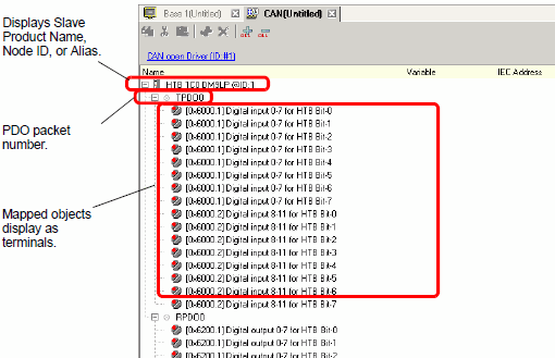
Objects set in [I/O Driver Settings] are reflected on the I/O Screen as terminals (I/O terminals). By allocating variables to terminals, I/O can be controlled.
![]()
When mapping TPDO4 or above and RPDO4 or above, the total slave settings are limited to 64.
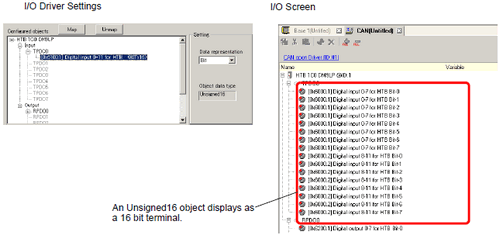
The terminal display on the I/O Screen differs depending on the type of each object (such as, Bit, Byte, Word, Dword) specified in the [Slave Configuration] dialog box in the [I/O Driver Settings].
Example 1: Set the Unsigned16 object "Digital input 0-11 for HTB" to "Bit" display settings.
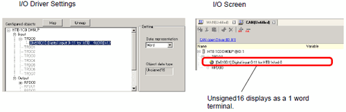
Example 2: Set the Unsigned16 object "Digital input 0-11 for HTB" to "Word" display settings.
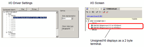
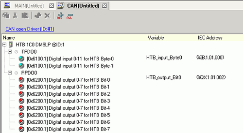
Example 3: Set the Unsigned16 object "Digital input 0-11 for HTB" to "Byte" display settings.
![]()
In "Digital input 0-11 for HTB", unsigned16 bit data lower bytes are allocated to the "Byte-0" terminal and higher bytes to the "Byte-1" terminal. The remaining bits of the assigned variables cannot be used.
When data type is "Byte" or "Word", the remaining bits of the assigned variables will not be used. Sign extension is not done to the unused higher bits.
Mapping Variables
Mapping a variable per terminal of objects. To define a variable, double-click the [Variable] column of the terminal you want to map.
The [IEC Address] is populated after entering a variable.
31.1.1.4 I/O Address Format
|
Data Type |
Input |
Output |
|
Bit |
IX |
QX |
|
Byte |
IB |
QB |
|
Word |
IW |
QW |
|
Dword |
ID |
QD |