![]()
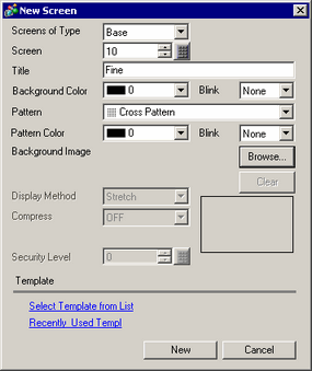
Please refer to the Settings Guide for details.
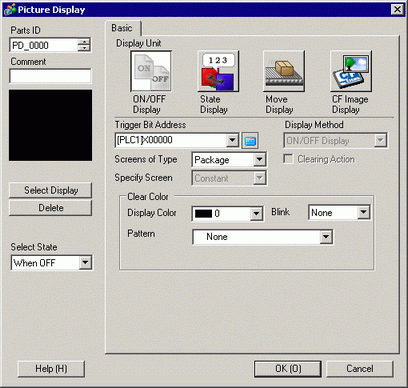
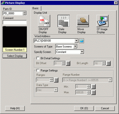
9.6.2.1 State Display - Basic Settings (Selecting a Package)
For details on how to draw parts, and defining the address, shape, color, and labels, please see the Editing Parts topic.
8.7.1 Editing Parts
On the [Screen (S)] menu, click the [New Screen (N)] command or click 
.
In [Screens of Type] select [Base], in [Screen] enter 10, and click [New].

Create a background on the screen to be called.

Draw a picture on the screen to be called.

Repeat steps 1 to 4 to create additional screens Base 11, Base 12, and Base 13.

![]()
To position a called screen, you specify where its center will be placed on the destination screen. Therefore, drawing your picture with a vertex at the center of the drawing area may make it easier to later position this picture on the destination screen.
Click the [Base 1] tab. From the [Parts (P)] menu, point to [Picture Display (F)] or click 
, and place the Picture Display anywhere on the screen.
Double-click within the border of the Picture Display part to open the Picture Display dialog box.

Select [State Display] and set up the [Word Address].
Set up the [Screens of Type] and [Specify Screen]. For example, in [Screens of Type] select [Base Screen], and in [Specify Screen] select [Constant].

Click [OK] to specify the position of the called pictures.

![]()