![]()
-
Please refer to the Settings Guide for details.
 14.11.2 Text Display
 -
For details on how to draw parts, and defining the address, shape, and color, refer to the following.
8.7.1 Editing Parts
![]()
Please refer to the Settings Guide for details.
![]() 14.11.2 Text Display
14.11.2 Text Display
For details on how to draw parts, and defining the address, shape, and color, refer to the following.
![]() 8.7.1 Editing Parts
8.7.1 Editing Parts
On the [Parts (P)] menu, select [Data Display (D)] and then click [Text Display (S)], or click ![]() and place it on the screen.
and place it on the screen.
Double-click the placed Data Display. The Data Display dialog box appears.
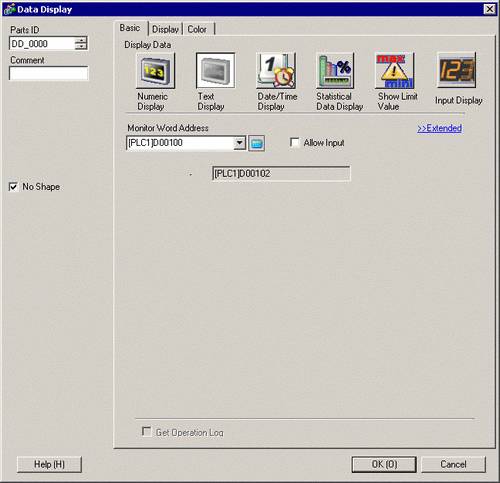
Select a part shape as necessary. Deselect [No Shape], and select a shape from [Select Shape].
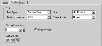
Click the [Display] tab, and enter the number of characters from 1 to 100 into the [Display Characters] field. When working with double-byte characters, each double-byte character counts as two characters.
![]()
If you want to change the display language according to the Text Data Table settings, from the [System Settings] window, [Display Unit] page's [Display] tab, select the [Synchronize Text Display language with Text Table] check box.
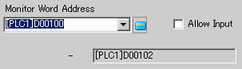
Click the [Basic] tab, and in [Monitor Word Address] set the address that stores the text display data.
The last address of the Word Address (Monitor Word Address + Display characters) displays.
![]()
Use two single-byte characters for one word, or one double-byte character for one word.
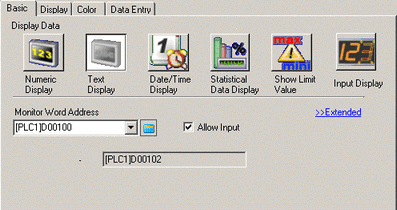
Select the [Allow Input] check box. The [Data Entry] tab is displayed.
![]()
This cannot be set when only text data displays.
Click the [Data Entry] tab and select the [Enable Popup Keypad] check box.
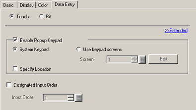
Set the font and/or color in the [Color] and [Display] tabs as necessary and click [OK].