Please refer to the Settings Guide for details.
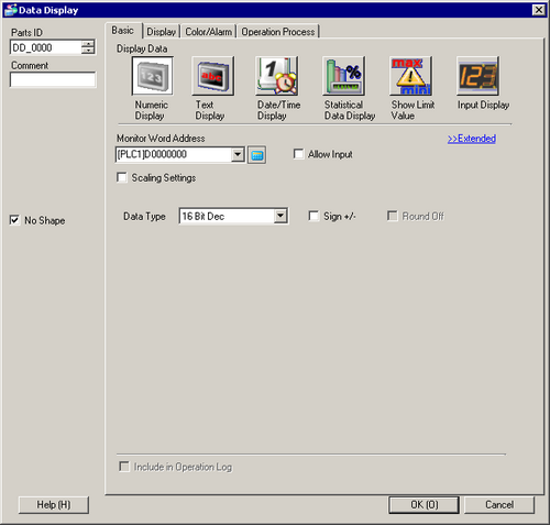
14.11.1 Numeric Display
For details on how to draw parts, and define the address, shape, and color, please see the following.
8.7.1 Editing Parts
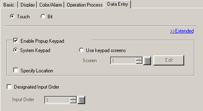
For information about the Input Order settings, refer to 14.13.1 Set Input Order.
From the [Parts (P)] menu, point to [Data Display (D)] and select [Numeric Display (N)], or click the icon, and place it on the screen.
Double-click the placed Data Display. The Data Display dialog box appears.
Select a part shape as necessary. Deselect [No Shape], and select a shape from [Select Shape].
In [Monitor Word Address], set up the address to store the displayed numeric value. (For example, D100)
In the [Data Type] drop-down list, set the type of data to display (for example, 16 Bit Dec).
Select the [Allow Input] check box. The [Data Entry] tab is displayed.
Click the [Data Entry] tab and select the [Enable Popup Keypad] check box.
Select the [Designated Input Order] check box, and specify the order in which the Part will enter the input state. (Example: 1)
Set the font and/or color in the [Color/Alarm] and [Display] tabs as necessary and click [OK].
In the same way, place the 2nd and the 3rd Data Displays and set appropriate [Monitor Word Address] and [Input Order] for each.