![]()
-
Please refer to the Settings Guide for details.
 14.11.1 Numeric Display
-
For details on how to draw parts, and define the address, shape, and color, please see the following.
8.7.1 Editing Parts
![]()
Please refer to the Settings Guide for details.
![]() 14.11.1 Numeric Display
14.11.1 Numeric Display
For details on how to draw parts, and define the address, shape, and color, please see the following.
![]() 8.7.1 Editing Parts
8.7.1 Editing Parts
From the [Parts (P)] menu, point to [Data Display (D)] and select [Numeric Display (N)], or click the ![]() icon, and place it on the screen.
icon, and place it on the screen.
Double-click the placed Data Display. The Data Display dialog box appears.
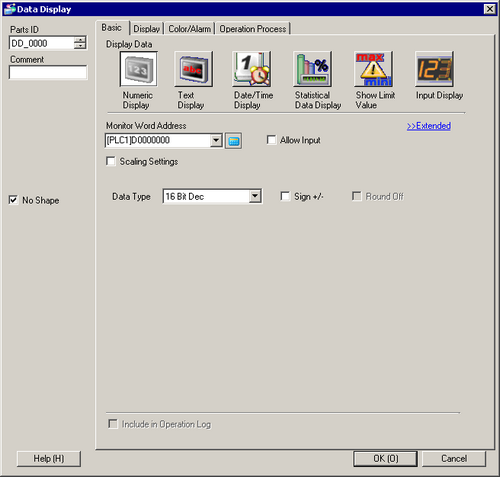
Select a part shape as necessary. Deselect [No Shape], and select a shape from [Select Shape].
In [Monitor Word Address], set up the address to store the displayed numeric value.
In the [Data Type] drop-down list, set the type of data to display (for example, 16 Bit Dec).
Select the [Allow Input] check box. The [Data Entry] tab is displayed.
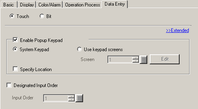
Click the [Data Entry] tab and select the [Enable Popup Keypad] check box.
Click the [Color/Alarm] tab, and select the [Alarm Settings] check box.
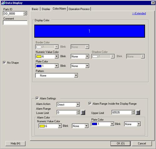
In the [Alarm Action] field, select the method used to define the Lower Limit and Upper Limit values (for example, [Direct]).
![]()
When selecting the [Alarm Range Inside the Display Range] check box, the settings are allowed only within the range defined in the [Basic] tab's [Display Range] area.
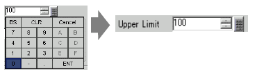
In [Alarm Range], set the Upper Limit (for example, 100) and Lower Limit (for example, 0).
Set the font and/or color in the [Color/Alarm] and [Display] tabs as necessary and click [OK].