Set the details of a device/PLC.
Add Device/PLC
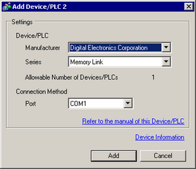
Adds the device/PLC settings. Use this setting when one display is communicating with multiple devices/PLCs.
Select [Manufacturer], [Series], and [Port].
![]()
The number of device/PLC drivers that the display unit can communicate with at the same time depends on the type of display unit.
![]() 1.5 Supported Features
1.5 Supported Features
When using a USB/RS-422/485 conversion adapter, select [USB/SIO(RS422/485)] for the [Port], and set the [Flow Control] to [None].
For a list of display modles that support the USB/RS-422/485 conversion adapter, please see the following:
![]() 1.5 Supported Features
1.5 Supported Features
Additionally, for devices you can connect with the the USB/RS-422/485 conversion adapter and its connection methods, refer to the "GP-Pro EX Device Connection Manual".
You cannot use multiple USB/RS-422/485 Conversion Adapters simultaneously.
Delete Device/PLC
Deletes the specified device/PLC.
Change Device/PLC
Changes the settings of the device/PLC.
![]() 7.9.1.1 Change Device/PLC Settings Guide
7.9.1.1 Change Device/PLC Settings Guide
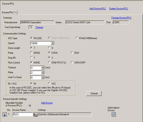
Summary
Displays the settings of the currently specified devices/PLCs.
Manufacturer
Displays the currently specified device/PLC maker.
Series
Displays the series of the currently set PLC.
Port
Displays the ports that can be connected to a device/PLC.
![]()
If the port is also used for other devices/PLCs, ![]() is displayed to the right of the [Port].
is displayed to the right of the [Port].
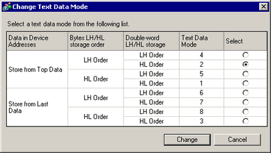
Displays the text data mode of the currently specified devices/PLCs.
Change
When the [Change Text Data Mode] dialog box is displayed, you can change the text data mode. Normally the text data mode is specified according to each device/PLC.
![]()
The USR memory storage order is fixed to [Text Data Mode] = 2, regardless of the actual setting of Text Data Mode.
Data in Device Addresses
Select the data device storage order from [Store from Top Data] or [Store from Last Data].
Storing the text "ABCDE"
Store from Start Data
When [Text Data Mode]=1
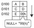
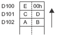
Store from Last Data
When [Text Data Mode]=3
LH/HL Storage
Select the data storage order in one word (16 bits), from either [LH Order] or [HL Order].
Storing the text "ABCDE"
HL Order
When [Text Data Mode]=1
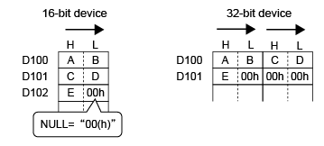
LH Order
When [Text Data Mode]=2
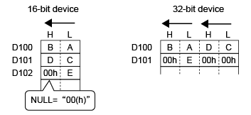
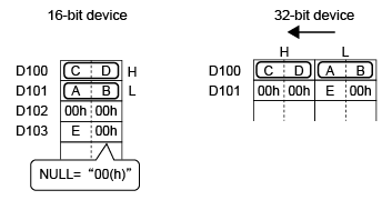
Double Word LH/HL Storage
Select the data storage order in two words (32 bits), from either [LH Order] or [HL Order].
Storing the text "ABCDE"
HL Order
When [Text Data Mode]=1
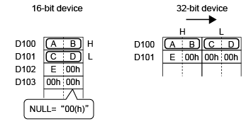
LH Order
When [Text Data Mode]=5
Text Data Mode
Displays the number associated with the Text Data Mode storage order.
Select
Select the text data mode to be used.
Communication Settings
Configure the settings according to the device/PLC.
For the settings, refer to the "GP-Pro EX Device/PLC Connection Manual".
![]()
It is recommended to keep the default settings for [Timeout], [Retry], and [Wait to Send].
When using PE-4000B, set up the communication format and flow control in the unit's BIOS settings. (Values set up in GP-Pro EX are ignored.)
Refer to the user manual for details on the set up process.
![]() PE4000B Series User Manual
PE4000B Series User Manual
See our website for details on setup values.
![]() http://www.pro-face.com/trans/en/manual/1039.html
http://www.pro-face.com/trans/en/manual/1039.html
Device-Specific Settings
Set this according to each device/PLC.
Allowable Number of Devices/PLCs
Displays the number of connectable units according to the type of the display unit specified.
Add Device
Each time you click the [Add Device], one device/PLC is added.
![]()
You cannot add the PLC if the [Allowable Number of Devices/PLCs] or the maximum number of sockets is reached the limit or if the total of PLCs and indirect devices is set up to 128.
Increase Allowable Number of Devices/PLCs
Displayed when you select devices/PLCs for which the number of allowable devices can be expanded. Click this button and the [Increase Allowable Number of Devices/PLCs] dialog box appears.
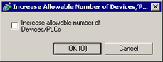
![]()
The number of connectable units can be expanded to 64 when the [Increase allowable number of Devices/PLCs] check box is selected.
![]() Delete Device/PLC
Delete Device/PLC
Deletes the device/PLC settings.
Device Name
Set the name of a device/PLC characters from 20 to 10 (single-byte).
![]()
Do not duplicate the device name.
The name cannot include a space or any of the following symbols.
+ - * / = % & ^ | \ : . , ” # ? @ [ ] < >
![]() Device/PLC Settings
Device/PLC Settings
Set individual settings as needed according to the device/PLC. Click the button to display the [Individual Device Settings] dialog box.
![]()
The [Individual Device Settings] differ depending on the PLC. For details on the settings of the device/PLC, see "GP-Pro EX Device Connection Manual."
Device ID
When using Indirect Device, and the series in the [Individual Device Settings] dialog box match the device/PLC, use this field to identify the device from 1 to 128.
Make sure you do not duplicate the Device ID with other indirect devices in the same driver. If the Device ID is duplicated, the ![]() warning icon appears beside the field.
warning icon appears beside the field.
![]() Add Indirect Device
Add Indirect Device
Set up the Indirect Device feature. Click this button to add a new indirect device to the list. You can add up to 64 indirect devices.
![]()
You can add up to a total 128 devices/PLCs and indirect devices to a single driver. However, the allowable number of devices/PLCs varies depending on the driver.
Indirect Device Name
Set the name of the indirect device with up to 20 single-byte characters (or 10 double-byte characters).
![]()
Do not duplicate device names.
The name cannot include a space or any of the following symbols.
+ - * / = % & ^ | \ : . , ” # ? @ [ ] < >
Device ID Address
When using indirect devices, the value in the Device ID Address identifies the device ID of the device/PLC to communicate with. You can only use the internal device addresses (LS area/USRS area).
![]()
If the Device ID Address stores a device ID with no associated device/PLC, the parts set to the indirect device will not work.
Initial ID
Right after the display unit is turned ON and the value in the [Device ID Address] is 0, use this field to specify which device/PLC to use from 1 to 128.
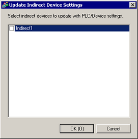
![]() Update Indirect Device Settings
Update Indirect Device Settings
Displays the [Update Indirect Device Settings] dialog box. If you change individual device settings after changing indirect devices, use this dialog box to update selected indirect devices with the new device/PLC settings.
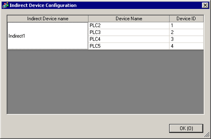
Indirect Device Configuration
Displays the [Indirect Device Configuration] dialog box. Use this dialog box to check the association between indirect devices, devices/PLCs, and device IDs.