![]()
-
Please refer to the Settings Guide for details.
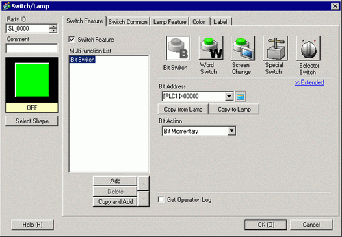
 10.15.1 Bit Switch
7.9 Settings Guide -
For details on how to draw parts and define the address, shape, color, and labels, please see the "Part Editing Procedure".
8.7.1 Editing Parts -
When the communication scan of device addresses on the screen is stopped, the special relay LS2032 (bit 1) and LS2033 (bit 1) do not automatically turn OFF.
-
You cannot stop the communication scan of a device specified with the System Area Start Address. However, if you are not using the System Data Area, you can stop the communication scan.
5.4.6 System Settings [Display Unit] - [System Area] Settings Guide -
When communication is interrupted (communication scan is stopped), an error occurs when a switch, script, logic program, Pro-Server EX, or other function attempts a write operation to the corresponding device/PLC. To remove the error, restart communication with the corresponding device.