![]()
-
Please refer to the Settings Guide for details.
 10.15.1 Bit Switch
7.9 Settings Guide -
For details on how to draw parts, and defining the address, shape, color, and labels, please see the parts editing topic.
8.7.1 Editing Parts
![]()
Please refer to the Settings Guide for details.
![]() 10.15.1 Bit Switch
10.15.1 Bit Switch
![]() 7.9 Settings Guide
7.9 Settings Guide
For details on how to draw parts, and defining the address, shape, color, and labels, please see the parts editing topic.
![]() 8.7.1 Editing Parts
8.7.1 Editing Parts
Create a lamp to acknowledge when a communication scan is running.
From the [Parts (P)] menu, point to [Switch Lamp (C)] and select [Lamp (L)] or click ![]() to place a lamp on the screen.
to place a lamp on the screen.
Double-click the placed lamp. The Switch/Lamp dialog box appears.
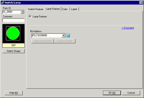
Use [Select Shape] to define the frame of the lamp.
Set the bit address to acknowledge the exclusive state of the communication scan in [Bit Address].
![]()
Use the internal device address LS9560 - LS9567 to acknowledge the execution or stop of the communication scan.
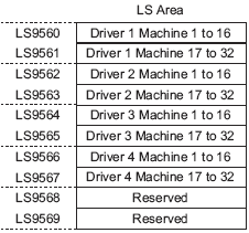
For example, you can acknowledge up to 16 communication scans of driver 1 using LS9560.
[LS9560]
![]()
Bit 0: OFF when the first I/O Driver1 is scanning. ON when the scan is stopped.
If you designate a 32-bit device in [System Area Start Address], you can set 32 bits in the LS area. However, you can only use the lower 16 bits to acknowledge the execution of the communication scan.
Click the [Color] tab and set the Lamp display colors. Set a [Display Color], [Pattern] and [Border Color] for each case where the [Select State] is ON or OFF.
![]()
Depending on the shape, you may not be able to change the color and pattern.
Click the [Label] tab. Define the label to appear on the Lamp. Specify the font type and size, and then in the rectangular field type the text to display. Click [OK].
![]()
When you select a switch and press the [F2] key, you can directly edit the text on the label.