![]()
-
Please refer to the Settings Guide for details.
 14.11 Data Display Settings Guide
16.6.1 System Settings [Input Equipment] Settings Guide -Bar Code 1/Bar Code 2
![]()
Please refer to the Settings Guide for details.
![]() 14.11 Data Display Settings Guide
14.11 Data Display Settings Guide
![]() 16.6.1 System Settings [Input Equipment] Settings Guide -Bar Code 1/Bar Code 2
16.6.1 System Settings [Input Equipment] Settings Guide -Bar Code 1/Bar Code 2
Configure settings to display the code data read from a barcode reader in Data Display and store it starting from the device/PLC's D100 address.
The following describes how to set up communication with barcodes. From the [Project] menu, select [System Settings], and click [Input Equipment] to open Input Equipment Settings dialog box.
From the [Type] drop-down list, select [Bar Code Reader].
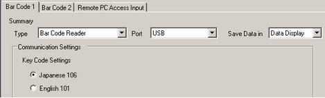
Select the port to connect from [USB/SIO(RS232C)], [USB], or a serial port, such as [COM1].
![]()
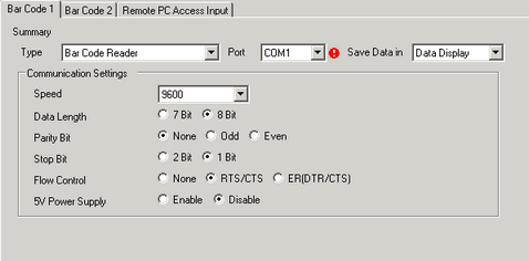
If the port is also used for other devices/PLCs, ![]() displays to the right of the [Port] as above.
displays to the right of the [Port] as above.
In [Communication Settings], set [Speed], [Data Length], [Parity], [Stop Bit], [Flow Control], and [5V Power Supply].
From [Save Data in], select [Data Display]. The settings for communicating with the barcode are complete.
On the drawing screen, configure the Data Display part that displays data from the barcode reader.
From the [Part (P)] menu, point to [Data Display (D)] and select [Text Display], or click ![]() to place a Data Display part on the screen.
to place a Data Display part on the screen.
Double-click the placed Data Display. The Data Display dialog box appears. Click [Text Display].
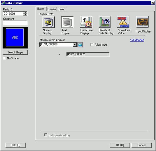
Click [Select Shape] and select the appropriate shape.
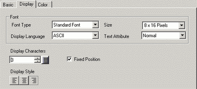
In the [Display] tab, define the number of single-byte characters in the [Display Characters] field, from 1 to 100. When working with double-byte characters, each double-byte character counts as two characters. (For example, "3” single-byte characters)
Click the [Basic] tab. In the [Monitor Word Address] field, set the address for where the value read from the barcode reader is stored. The last address of the Word Address (Monitor Word Address + Display characters) displays
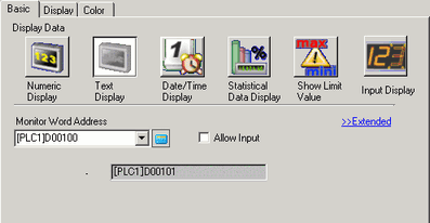
![]()
Use two single-byte characters for one word, or one double-byte character for one word. In the above example, two words are used because, in Step 9, [Display Characters] is set to 3 single-byte characters.
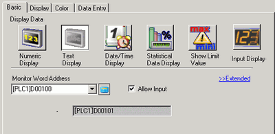
Select the [Allow Input] check box. Selecting [Allow Input] displays the [Data Entry] tab where you can enter text data.
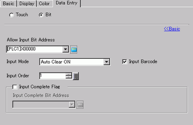
Click the [Data Entry] tab and select [Extended].
Select [Bit] for the input type and set [Allow Input Bit Address]. Data input from a bar code reader is enabled when this bit address is ON.
Select [Input Barcode]and select the processing method to overwrite the read code data from [Input Mode].
If necessary, set the Data Display color in the [Color] tab or text in the [Display] tab, and click [OK].
![]()
You have to set the bit switch to permit input for Data Display.
![]() 10.3 Inverting a Bit ON/OFF
10.3 Inverting a Bit ON/OFF
One barcode reader can be connected to either a serial port, such as COM1, or USB port.
When connecting two barcode readers at the same time, store data in separate locations of [Save Data in] from [Data Display] and [Internal Device] or use different storing address by selecting [Internal Device].
If both devices choose to save data in the [Data Display], the system may not work properly.
If [Input Barcode] is not set in the [Data Entry] tab for the Data Display, the read code data is not written to the Data Display.
If the number of the read code data exceeds the [Display Characters] set for a Data Display, the data cannot be properly displayed on the Data Display. The maximum number of display characters that can be set in a Data Display is 100 (single-byte) characters.