With the Video Module installed, pictures taken from four angles are displayed on the display unit's screen in real time.
-
In [System Settings], select [Image Unit].

If the [System Settings] tab is not displayed in the workspace, on the [View (V)] menu, point to [Workspace (W)], and then click [System Settings (S)].
-
In the [Image Input Module Settings], confirm whether [VM Unit 2000] or [VM Unit 3000] is selected.
For [Video Control Start Address] select [Disable]. For [Video Input] select [NTSC]. (If the video signal is PAL, select [PAL].)
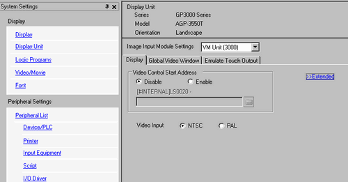
If the [Video Control Start Address] is set to [Enable], 42 Words from the setup control address are automatically used to control the video display. For the items in the video control, see the following.
 27.11 Video Control Area
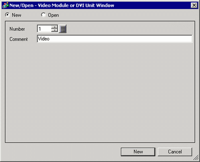
On the [Common Settings (R)] menu, select [Image Unit Window (U)] or click  to open the following dialog box. Select [New] and then specify [Number] and [Comment]. (For example, Number "1", Comment "Image Unit Window")
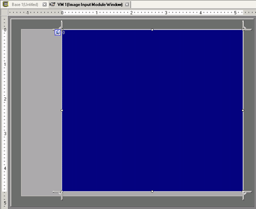
The video window [VM1] appears.
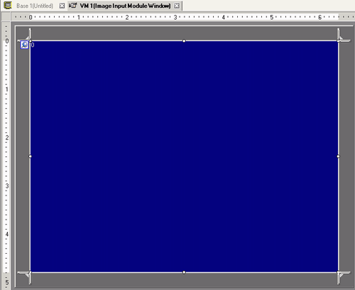
Adjust the [Image Unit Window] size.
To reduce the Window Screens, first reduce the display area (blue parts), then drag the  mark on the four corners to adjust the size. To enlarge, expand the window size and adjust the display area to fit the window size.
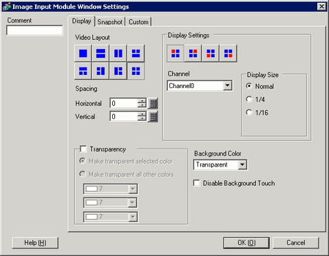
Double-click the blue display area. The following dialog box appears. In [Video Layout] click  .
.
-
In the [Display] area, click  , and under the [Channel], select the camera image to be displayed in this upper left area (for example, Channel 0).
Also select the size of the image (for example, 1/4).
Similarly, select the channels and display sizes for the images displayed in the upper right, lower left, and lower right areas.
If the selected [Display Size] is larger than the display unit or the blue display area, the entire image will not display. You can use [Video Display position] on the [Custom Settings] tab to specify which part of the input image to be displayed. If you want to display the entire image, set the [Display Size] smaller than the size of the blue display area.
The display size varies depending on a type of display unit and display mode.
27.12.1 Display Size - Video Module
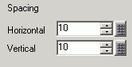
Specify the values for the space between the screens. (For example, Horizontal 10, Vertical 10)
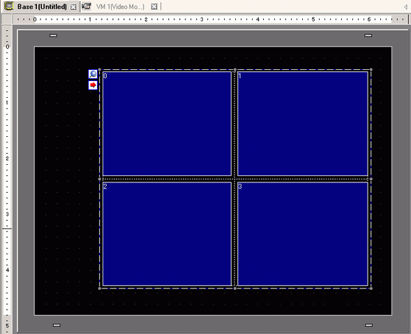
Click [OK] to finish and exit the [Image Unit Window] settings.
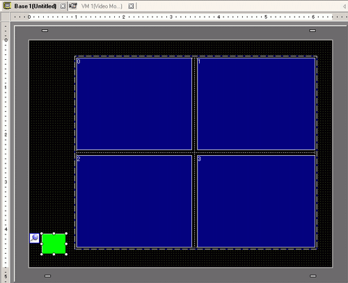
Click the [Base 1] tab to display the base screen.
On the [Parts (P)] menu, select [Image Unit Display (V)] or click  to place the [Image Unit Display] on the screen.
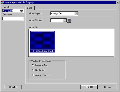
Double-click the [Image Unit Display]. The following dialog box appears.
-
In the [Video Layout] list, click [ON/OFF display] and select the video screen number (for example, 1) in the [Video Number].
Under [Window Interchange], select [Move to Top].
In the [Window Display Bit Address] list, set the bit address for controlling the window display and click [OK].
Place a switch on the screen to display/delete the [Image Unit Window].
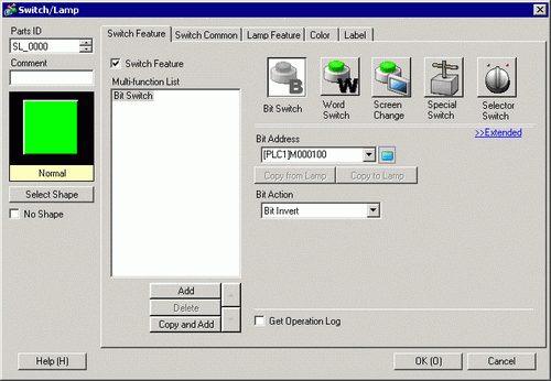
On the [Parts (P)] menu, point to [Switch Lamp], and select [Bit Switch (B)], or click  to place a switch on the screen.
Double-click the switch. The following dialog box appears.
In the [Bit Address] list, select the (M100) address for controlling the screen and select [Bit Invert] in the [Bit Action] list.