In [IO Driver Settings] click [Settings] and add HTB to the network.![]() 30.7.1 Setup Flow - CANopen
30.7.1 Setup Flow - CANopen
Click [Slave Settings] while the additional HTB is selected, and the following dialog box appears.
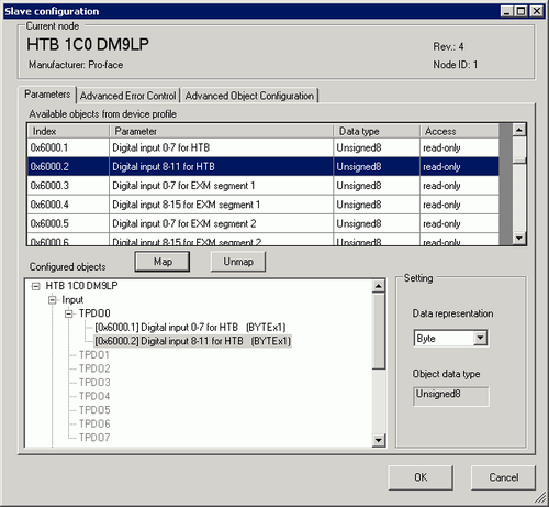
While [TPDO0] is selected, select [0x6000.1] and then click the [Map] button.
Map [0x6000.2] to [TPDO0].
Check whether [0x6000.1] and [0x6000.2] have been allocated.
To change the data type of the object in TPDO, select the object and then select [Data representation] in [Settings]. For example, Bit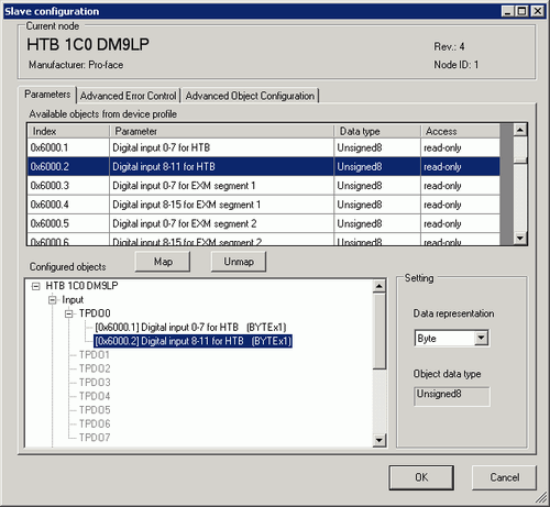
Open the PRDO0 and map [0x6200.1] to [PRDO0].
To change the data type of the object in RPDO, select the object and then and select [Data representation] in [Settings]. For example, Bit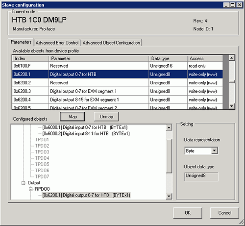
![]()
Map the input data from HTB (CANopen slave) to the display unit (CANopen master) for PDO, and map the object relating to the output data from the display unit to HTB for RPDO.
When mapping TPDO4 or above and RPDO4 or above, the total slave settings are limited to 64.
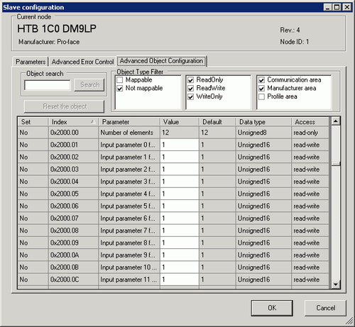
Open the [Advanced Object Configuration] tab to configure the object values. Set the input filter (0x2000.1 to 0x2000.C), the fallback mode (0x6306.1) and the fallback value (0x6307.1) as required and click [OK] to close the dialog.
![]()
For details of objects, refer to the following.
 30.7.10 Communication Setting HTB Objects (1000h to 1FFFh)
To assign variables to each mapped object, in [I/O Driver] click [I/O Screen], or from the Workspace menu select [Screen List] and then click the I/O screen. For information on how to assign variables, refer to the following.![]() 30.7.3 Mapping I/O - CANopen
30.7.3 Mapping I/O - CANopen
Create a Logic Screen and a Base Screen to access the allocated variables and transfer them to the display unit.
![]()
To check set values, use SDOR instructions.