![]()
Please refer to the Settings Guide for details.
 13.7 Lamp Settings Guide
For details on how to draw parts, and defining the address, shape, color, and labels, please see the parts editing topic.
8.6.1 Editing Parts
![]()
Please refer to the Settings Guide for details.![]() 13.7 Lamp Settings Guide
13.7 Lamp Settings Guide
For details on how to draw parts, and defining the address, shape, color, and labels, please see the parts editing topic.![]() 8.6.1 Editing Parts
8.6.1 Editing Parts
In the following procedure, error information from a device/PLC is mapped to each bit in a word address (D100). When an error occurs, the corresponding word address bit turns ON and a lamp set up with that same word address displays its associated color.
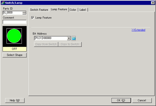
From the [Parts (P)] menu, point to [Switch Lamp (C)] and select [Lamp (L)] or click ![]() to place a lamp on the screen.
to place a lamp on the screen.
Double-click the placed lamp. The Switch/Lamp dialog box appears. Click [Extended].
Set the [Number of States] and [State Switch Condition]. Setting the [Number of States] to 3 or more allows you to set [State Switch Condition].
(For example, [Number of States] = 17, [State Switch Condition] = Change Condition by Bit)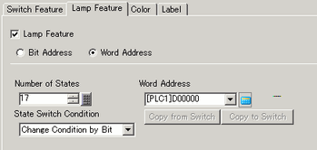
Specify the address to display the color coding of the lamp in [Word Address]. (For example, D100)
In [Select Shape], select the lamp shape for each [State].
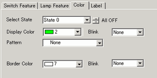
Click the [Color] tab. In the [Select State] list, select [State 0] and define its [Display Color].
[State 0] is the state where all the specified bit addresses are OFF.
![]()
Each [State] is defined as the ON (1)/OFF (0) of the corresponding bit address.]
|
State |
Description |
|---|---|
|
[State 0] |
All 0 |
|
[State 1] |
Only Bit 00 is 1. |
|
[State 2] |
Only Bit 01 is 1. |
|
[State 3] |
Only Bit 02 is 1. |
|
[State 4] |
Only Bit 03 is 1. |
|
[State 5] |
Only Bit 04 is 1. |
|
[State 6] |
Only Bit 05 is 1. |
|
[State 7] |
Only Bit 06 is 1. |
|
[State 8] |
Only Bit 07 is 1. |
|
[State 9] |
Only Bit 08 is 1. |
|
[State 10] |
Only Bit 09 is 1. |
|
[State 11] |
Only Bit 10 is 1. |
|
[State 12] |
Only Bit 11 is 1. |
|
[State 13] |
Only Bit 12 is 1. |
|
[State 14] |
Only Bit 13 is 1. |
|
[State 15] |
Only Bit 14 is 1. |
|
[State 16] |
Only Bit 15 is 1. |
When multiple bits turn ON at the same time, a lamp display appears in the ascending order from [Bit 0] to [Bit 15], giving priority to the smallest number.
Select [State 1] in [Select State] and set the [Display Color]. [State 1] is the state where Bit 0 of Word Address D100 is ON.
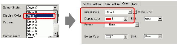
Set [Display Color] for states, from [State 2] to [State 16].
![]()
When clicking the button beside [Select State]![]() , you can change the state without displaying a list.
, you can change the state without displaying a list.
Depending on the shape, the color setup procedure may differ from the procedure described above. Click [Select Shape]. The [Select State] window appears. Select each state and click [Open] to select a shape and color.
Depending on the shape, you may not be able to change the color.
Click the [Label] tab and define the label for each state. Specify the font type and size, then type the text and click [OK].
![]()
When you select a lamp and press the [F2] key, you can directly edit the text on the label.