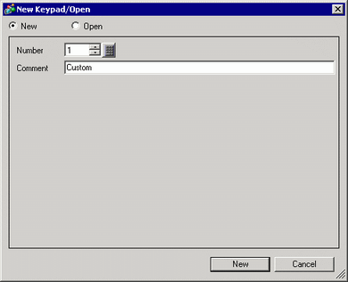
From the [Common Settings (R)] menu, select [Keypad Registration (K)]. The [New Keypad/Open] dialog box appears.
Set the [Number] and [Comment] and then click [New]. (For example, [Number] 1, [Comment] Custom)
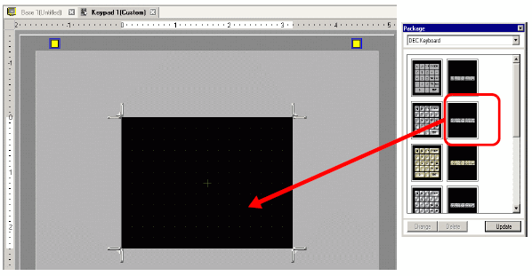
The screen to create the keypad [Clear Area] appears.
-
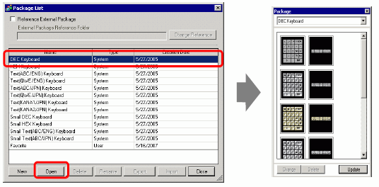
From the [View (V)] menu, select [Package (P)], or click  to display the [Package List] dialog box.
Select the package name (for example, DEC Keypad) that is registered with the keypad you want to use, click [Open], and the [Package] dialog box appears.
Select a keypad to use and place it on the [Clear Area].
-
Create the keypad [Clear Area]. Drag the [Resize Boundary]  in the four corners of the [Clear Area] setting screen to change the size. The [Resize Boundary] button you drag with the mouse cursor determines the direction in which the clear area size changes.
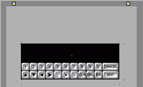
Customize the keypad as needed, such as modifying the key layout and size.
-
Place a part for Input display on the customized keypad. From the [Parts (P)] menu, point to [Data Display (D)] and select [Input Display (I)] to place it on the screen.
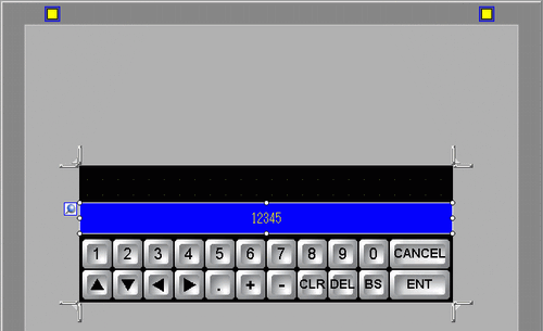
Double-click the placed Input display part to open the setting dialog box.
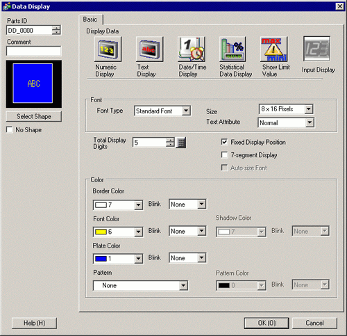
If necessary, set the color of the Input display part and text to be displayed, and click [OK].
-
Place a part for Limit Value display on the customized keypad. From the [Parts (P)] menu, point to [Data Display (D)] and select [Show Limit Value (W)] to place it on the screen.
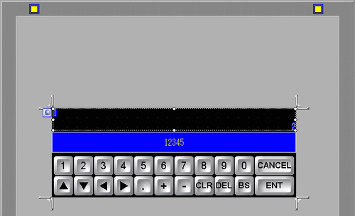
Double-click the placed Limit Value display part to open the setting dialog box.
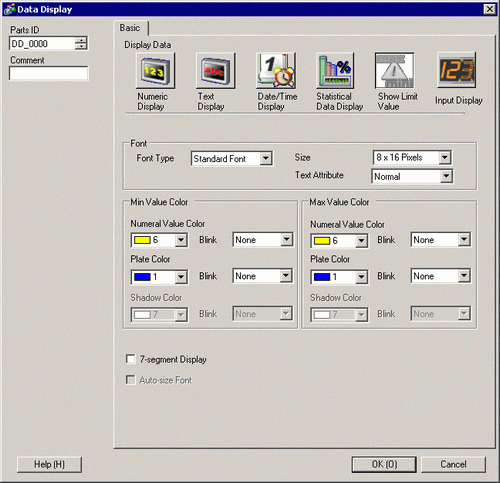
As needed, set the color of the Limit Value display part and text to be displayed, and click [OK].
Click the [Base 1] tab to move to the base screen.
Configure settings to use the custom keypad with a Data Display. From the [Parts (P)] menu, point to [Data Display (D)] and select [Numeric Display (N)], or click the  icon, and place it on the screen.
Double-click the placed element. The Data Display dialog box appears.
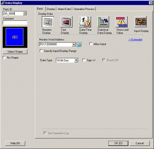
Click [Select Shape] and select the appropriate shape.
In [Monitor Word Address], set up the address to store the numeric value.
In the [Data Type] drop-down list, set the type of data to display.
Select the [Allow Input] check box. Once you select the [Allow Input] check box, the [Data Entry] tab appears and you can enter numeric data.
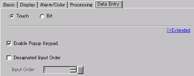
Click the [Data Entry] tab and the following appears. Select the [Enable Popup Keypad] check box.
Specifies whether or not to keep the output when the logic program is off
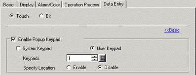
In the [Extended] screen, select the [User Keypad] check box and set the [Keypad] screen number (for example, 1) with the keypad setting to the [Keypads].
As needed, specify the Data Display's color and text on the [Alarm/Color] tab and [Display] tab, and click [OK].
 15.6.2.1 Keypad Registration - New