![]()
Please refer to the Settings Guide for details.
 17.10.1.1 Direct Input - Basic
For details on how to draw parts, and defining the address, shape, color, and labels, please see the parts editing topic.
8.6.1 Editing Parts
![]()
Please refer to the Settings Guide for details.![]() 17.10.1.1 Direct Input - Basic
17.10.1.1 Direct Input - Basic
For details on how to draw parts, and defining the address, shape, color, and labels, please see the parts editing topic.![]() 8.6.1 Editing Parts
8.6.1 Editing Parts
From the [Parts (P)] menu, select [Message Display (M)] or click ![]() . Place the Part on the screen.
. Place the Part on the screen.
Double-click the new Message Display. The following dialog box appears.
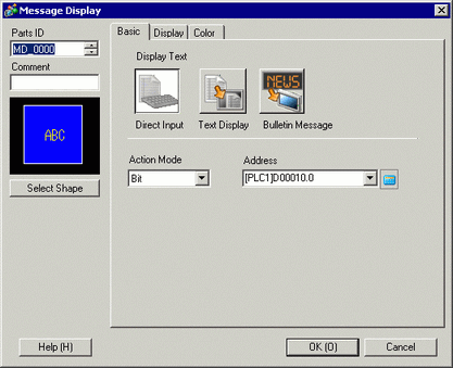
In the [Mode] drop-down list, select the method for changing messages. (For example, Word)
In [Address], set the address to trigger the message display..
Click the [Display] tab. In the [Text Type] section, select [Direct Text].
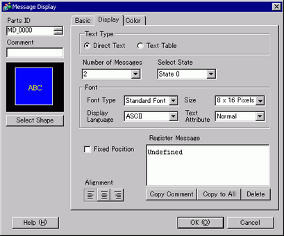
In the [Number of Messages] drop-down list, set the number of messages to display. For example, 4
Set the message Font Type, Size, and Display Language.
In the [Align] section, set the text position. (For example, Center)
Set the message for each state.
In the [Select State] drop-down list, select [State 0] and type the message in the [Register Message] box.
(If this box is left blank, the message displays nothing.)
In the [Select State] drop-down list, select [State 1] and type "Abnormal Pressure" in the [Register Message] box.
(When State 1 is stored in [Address], "Abnormal Pressure" displays.)
In the [Select State] drop-down list, select [State 2] and type "Confirm Rack Enabled" in the [Register Message] box.
(When State 2 is stored in [Address], "Confirm Rack Enabled" displays.)
As needed, set the Text Color and Plate Color for each state on the [Color] tab, and click [OK (O)].
![]()
If you select a message that has not been defined, the Message Display shows nothing. For example, if the number of message states is 16 and only states 0 to 3 have messages defined, states 4 to 16 display only the empty message frame.
You can type up to 100 single-byte characters for each message. Any characters over 100 are not displayed in the message.