Please refer to the Settings Guide for details.
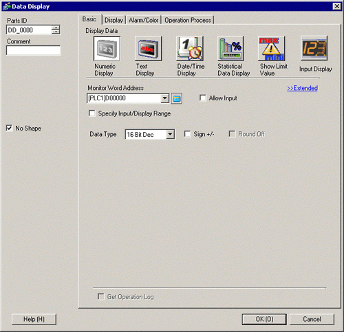
14.11.1 Numeric Display
For details about placing parts or setting addresses, shapes, or colors, please see the following.
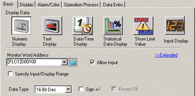
8.6.1 Editing Parts
For information about the Input Order settings, refer to 14.13.1 Set Input Order.
From the [Parts (P)] menu, point to [Data Display (D)] and select [Numeric Display (N)], or click the icon, and place it on the screen.
Double-click the placed Data Display. The following dialog box appears.
Select the Data Display shape from [Select Shape].
In [Monitor Word Address], set the address that will store the display value..
In the [Data Type] drop-down list, select the type of data to display (for example, "16 Bit Dec").
Select the [Allow Input] check box. Ensure the [Enable Popup Keypad] check box is selected. You can enter numerical data from the pop-up keypad.
In the [Data Entry] tab, select the [Allow Input] check box.
In [Input Order], set the order the part will enter input status (for example, 1).
As needed, set the Data Display color and text on the [Alarm/Color] tab and [Display] tab, and click [OK].
In the same way, to set the 2nd Data Display that will enter the Allow Input state, set [Monitor Word Address] to "D101", and [Input Order] to "2". For the 3rd Data Display that will enter the Allow Input state, set [Monitor Word Address] to "D102", and [Input Order] to "3".