![]()
Please refer to the Settings Guide for details.
 14.11.1 Numeric Display
For details about placing parts or setting addresses, shapes, or colors, please see the following.
8.6.1 Editing Parts
![]()
Please refer to the Settings Guide for details.![]() 14.11.1 Numeric Display
14.11.1 Numeric Display
For details about placing parts or setting addresses, shapes, or colors, please see the following.![]() 8.6.1 Editing Parts
8.6.1 Editing Parts
From the [Parts (P)] menu, point to [Data Display (D)] and select [Numeric Display (N)], or click the ![]() icon, and place it on the screen.
icon, and place it on the screen.
Double-click the placed Data Display. The following dialog box appears.
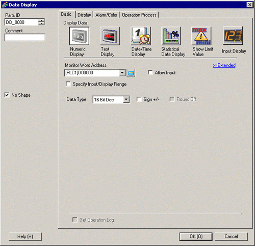
Select the Data Display shape from [Select Shape].
In [Monitor Word Address], set the address that will store the Value to display..
In the [Data Type] drop-down list, select the type of data to display (for example, "16 Bit Dec").
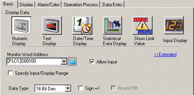
Select the [Allow Input] check box. Ensure the [Enable Popup Keypad] check box is selected. You can enter numerical data from the pop-up keypad.
Click the [Alarm/Color] tab, and select the [Alarm Settings] check box.
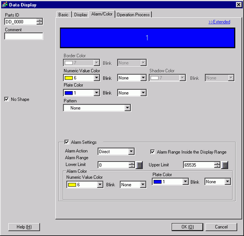
In the [Alarm Action] field, select the method used to define the Lower Limit and Upper Limit values from either [Direct] or [Address] (for example, [Direct]).
![]()
When selecting the [Alarm Range Inside the Display Range] check box, the settings are allowed only within the range defined in the [Basic] tab's [Display Range] area.
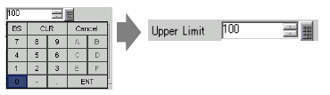
In [Alarm Range], set the Upper Limit (for example, 100) and Lower Limit (for example, 0).
As needed, set the Data Display color and text on the [Alarm/Color] tab and [Display] tab, and click [OK].
![]()
There are no input restrictions on the values input from the PLC.