![]()
Please refer to the Settings Guide for details.
 14.11 Data Display Settings Guide16.4.1 Input Equipment (Bar Code 1/Bar Code 2) Settings
![]()
Please refer to the Settings Guide for details.![]() 14.11 Data Display Settings Guide
14.11 Data Display Settings Guide![]() 16.4.1 Input Equipment (Bar Code 1/Bar Code 2) Settings
16.4.1 Input Equipment (Bar Code 1/Bar Code 2) Settings
Configure settings to display the code data read from a barcode reader in Data Display parts and store it starting from the device/PLC's D100 address.
The following describes how to set up communication with barcodes. From the System Settings, click [Input Equipment] to display the following screen.
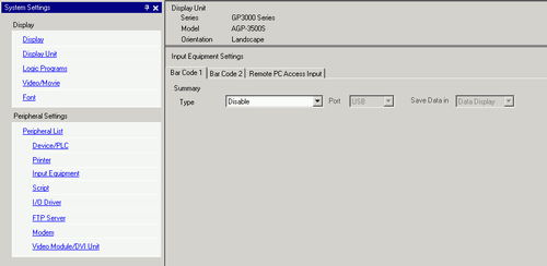
From the [Type] drop-down list, select [Bar Code Reader].
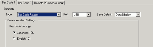
In the [Port] drop-down list, select the port to which you want to connect.
![]()
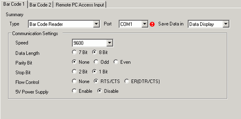
If the port is also used for other devices/PLCs, ![]() displays to the right of the [Port] as above.
displays to the right of the [Port] as above.
In [Communication Settings], set [Speed], [Data Length], [Parity], [Stop Bit], [Flow Control], and [5V Power Supply].
From the [Save Data In] drop-down list, select a data storage location. The settings for communicating with the barcode are complete.
On the drawing screen, configure the Data Display part that displays data from the barcode reader.
From the [Part (P)] menu, point to [Data Display (D)] and select [Text Display], or click ![]() to place a Data Display part on the screen.
to place a Data Display part on the screen.
Click the Data Display part, and the following dialog box appears. Click [Text Display].
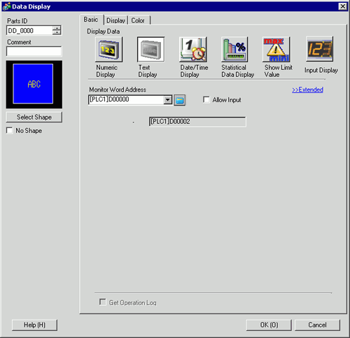
Select the Data Display shape from [Select Shape].
In the [Display] tab, define the number of single-byte characters in the [Display Characters] field, from 1 to 100. When working with double-byte characters, each double-byte character counts as two characters. (For example, "3" single-byte characters)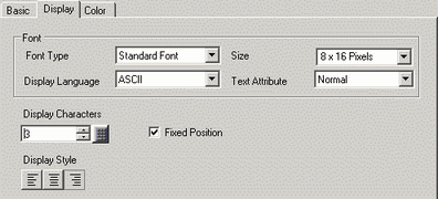
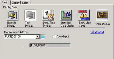
Click the [Basic] tab. In the [Monitor Word Address] field, set the address for where the value read from the barcode reader is stored.
The address from the [Monitor Word Address] displays.
![]()
Use two single-byte characters for one word, or one double-byte character for one word. In the above example, two words are used because, in Step 9, [Display Characters] is set to 3 single-byte characters.
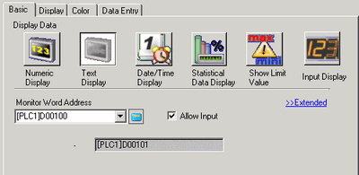
Select the [Allow Input] check box. Selecting [Allow Input] displays the [Data Entry] tab where you can enter text data.
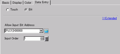
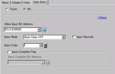
Click the [Data Entry] tab, and select [Bit] for the input method.
Set the [Allow Input Bit Address]. Data input from a bar code reader is enabled when this bit address is ON.
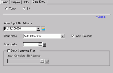
Click [Extended] and select the [Input Barcode] check box.
From the [Input Mode] drop-down list, select the processing method to overwrite the read code data.
If necessary, set the Data Display part's color in the [Color] tab or text in the [Display] tab, and click [OK].
![]()
You have to set the bit switch to permit input for Data Display parts.![]() 10.3 Inverting a Bit ON/OFF
10.3 Inverting a Bit ON/OFF
One barcode reader can be connected to either the COM1 or USB port, but when connecting two barcode readers at the same time and storing the code data from both bar codes in Data Display parts or the internal device, the system may not work properly. One barcode reader should be set up to read data from the Data Display part, and the other barcode reader should be set up to store data to the internal device.
If [Input Barcode] is not set in the [Data Entry] tab for the Data Display part, the read code data is not written to the Data Display part.
If the number of the read code data exceeds the [Display Characters] set for a Data Display part, the data cannot be properly displayed on the Data Display part. The maximum number of display characters that can be set in a Data Display part is 100 (single-byte) characters.